Eureka AIR delivers breakthrough ideas for toughest innovation challenges, trusted by R&D personnel around the world.

Method and device for aftertreatment of exhaust gases of internal combustion engines

An internal combustion engine and reprocessing technology, which is applied to the electronic control of exhaust treatment devices, mechanical equipment, exhaust treatment, etc., can solve the problem of expensive sensor devices, failure to reach the regeneration temperature of the regenerated particulate filter, and nitrogen oxides that cannot be catalyzed in three ways Converter conversion and other issues to achieve the effect of avoiding the remaining loading

Active Publication Date: 2021-04-09
VOLKSWAGEN AG
View PDF13 Cites 0 Cited by
  • Summary
  • Abstract
  • Description
  • Claims
  • Application Information

AI Technical Summary

Problems solved by technology

Furthermore, expensive sensor devices are required to monitor and control regeneration
However, the disadvantage with this lean combustion control is that the regeneration temperature required for regeneration of the particulate filter is not reached just in low part load operation and during short trips
Furthermore, during the lean-burn regulation of the engine, nitrogen oxides cannot be sufficiently converted by the three-way catalytic converter because no reducing agent for nitrogen oxides is present

Method used


Image

  • Method and device for aftertreatment of exhaust gases of internal combustion engines
  • Method and device for aftertreatment of exhaust gases of internal combustion engines
  • Method and device for aftertreatment of exhaust gases of internal combustion engines

Examples


Embodiment Construction

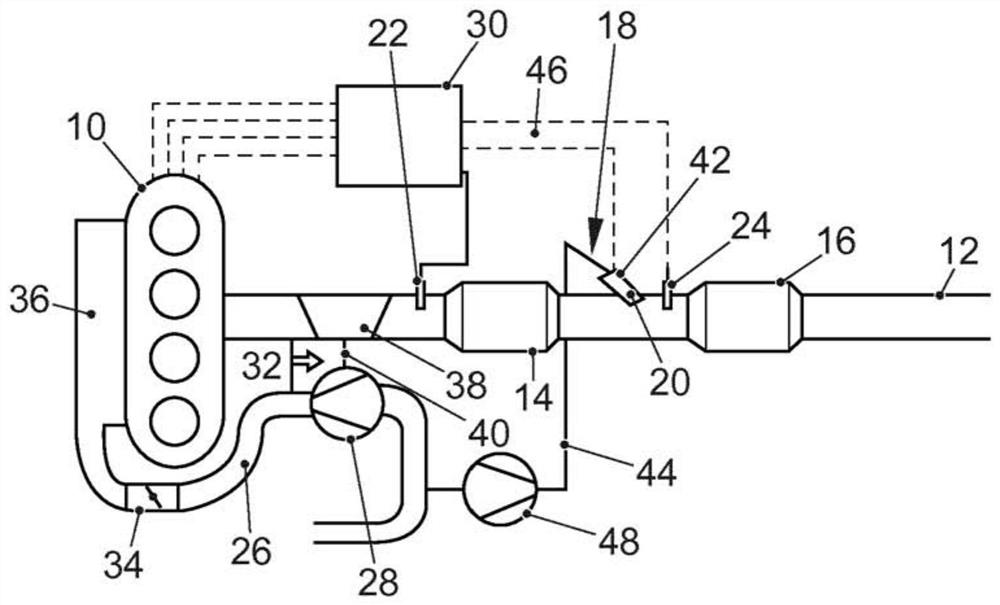
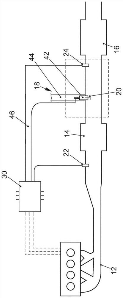
[0033] figure 1 An internal combustion engine 10 in the form of a gasoline engine equipped with a turbocharger 32 is shown having an intake duct 26 and an exhaust gas duct 12 . A compressor 28 , a throttle valve 34 and a charge air cooler 36 are arranged in the intake passage 12 . Arranged in the exhaust gas duct 12 in the flow direction of the exhaust gas of the internal combustion engine 10 is a turbine 38 of a turbocharger 32 which drives a compressor 28 of the turbocharger 32 via a drive shaft 40 . Alternatively, the compressor 28 can also be designed as a mechanically driven compressor or as an electric compressor.

[0034] Downstream of the turbine 38 in the flow direction of the exhaust gas of the internal combustion engine 10 through the exhaust gas passage 12 , a three-way catalytic converter 14 is arranged in the exhaust gas passage 12 . In this case, the three-way catalytic converter 14 is preferably arranged close to the engine in order to enable rapid heating of...


PUM


Abstract

The invention relates to a method for exhaust gas aftertreatment of an internal combustion engine, in particular for regenerating a particle filter in the exhaust gas duct of the internal combustion engine, wherein the particle filter is loaded with soot particles during normal operation of the internal combustion engine. In order to reach the regeneration temperature of the particulate filter, the internal combustion engine is operated with a fuel-rich mixture and at the same time secondary air is introduced into the exhaust gas duct, wherein the unburned fuel components are converted exothermicly on the particulate filter with the secondary air until the particulate The filter is heated up to regeneration temperature. If the regeneration temperature is reached, the internal combustion engine is operated with a stoichiometric combustion air ratio and secondary air for oxidizing the soot particles trapped in the particle filter is blown into the exhaust gas channel, wherein the secondary air quantity is adjusted by λ The probing takes place downstream of the point of introduction for the secondary air and upstream of the particle filter.

Description

technical field [0001] The invention relates to a method and a device for aftertreatment of exhaust gases of internal combustion engines. Background technique [0002] The continuous tightening of exhaust gas emission regulations places high demands on vehicle manufacturers, which are met by corresponding measures for reducing the original engine emissions and by corresponding exhaust gas aftertreatment devices. With the introduction of the next legal phase EU6, limit values ​​for the number of particulates are also prescribed for gasoline engines. What this can cause is that, in some models, it may be necessary to use a gasoline particulate filter. During driving operation, such gasoline particulate filters are loaded with soot. In order for the exhaust gas back pressure to not rise too strongly, the gasoline particulate filter must be regenerated continuously or periodically. In order to carry out the thermal oxidation of the soot trapped in the gasoline particulate fil...

Claims


Application Information

Patent Timeline
Patent Type & Authority Patents(China)
IPC IPC(8): F01N9/00F01N3/021F01N3/10F01N3/22
CPCF01N3/101F01N3/225F01N9/002F01N3/021F01N2430/06F01N2550/14F01N2560/025F01N2560/06F01N2610/085F01N2900/0416F01N2900/1402F01N2900/1404F01N2900/1602F01N2900/1606Y02T10/12Y02T10/40F01N3/2006F01N9/00F01N11/002F01N2560/05F01N2560/07F01N2900/0408G01M15/104
Inventor F.津克
Owner VOLKSWAGEN AG
Why Eureka
Eureka Blog
Learn More