Eureka AIR delivers breakthrough ideas for toughest innovation challenges, trusted by R&D personnel around the world.

A computer-controlled laser processing device and processing method thereof

A laser processing and computer technology, applied in the direction of manufacturing tools, metal processing equipment, laser welding equipment, etc., can solve the problems of unfavorable cutting speed and flexibility, and the failure of cut single pieces, so as to prevent improper operation and reduce cracks and debris, precisely controlled effects

Active Publication Date: 2020-10-02
ZIBO VOCATIONAL INST
View PDF10 Cites 0 Cited by
  • Summary
  • Abstract
  • Description
  • Claims
  • Application Information

AI Technical Summary

Problems solved by technology

[0002] The cutting of silicon wafers or other semiconductor wafers often adopts mechanical cutting or laser cutting, and laser cutting has the beneficial effect of preventing the risk of fragments and cracks; however, existing laser cutting devices can only cut one dividing line at a time, or cut The spacing of multiple cutting lines is fixed, which is not conducive to the speed and flexibility of cutting; in addition, if the laser head or laser system is inclined in the vertical direction, that is, it is not perpendicular to the silicon wafer, then the cutting line Slanting can also occur, which can lead to failure of the cut single piece

Method used


Image

  • A computer-controlled laser processing device and processing method thereof
  • A computer-controlled laser processing device and processing method thereof
  • A computer-controlled laser processing device and processing method thereof

Examples


Embodiment Construction

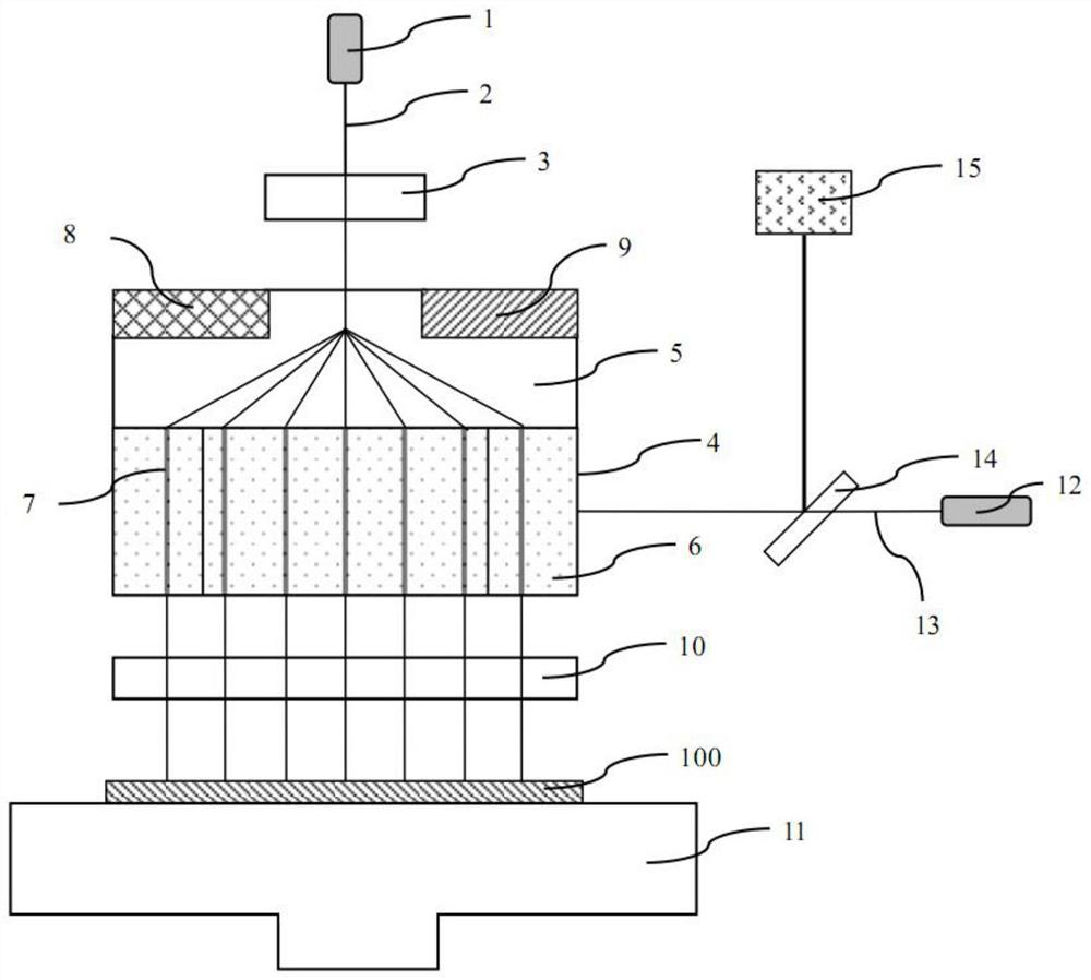
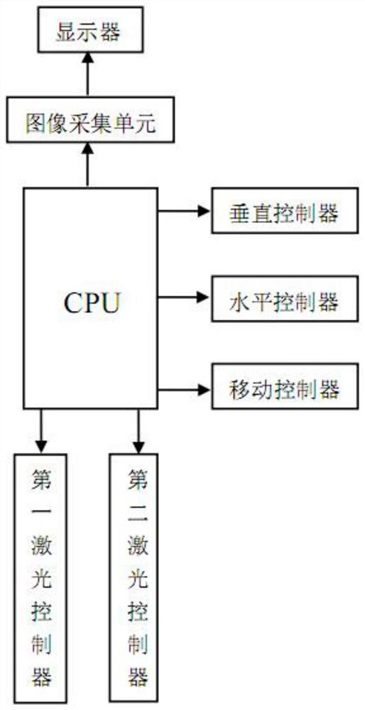
[0032] see figure 1 , the computer-controlled laser processing device of the present invention comprises:

[0033] a first laser 1 emitting a first laser beam 2 along a first optical axis;

[0034] A second laser 12, the second laser 12 emits a second laser beam 13 along a second optical axis, and the first optical axis and the second optical axis are perpendicular to each other;

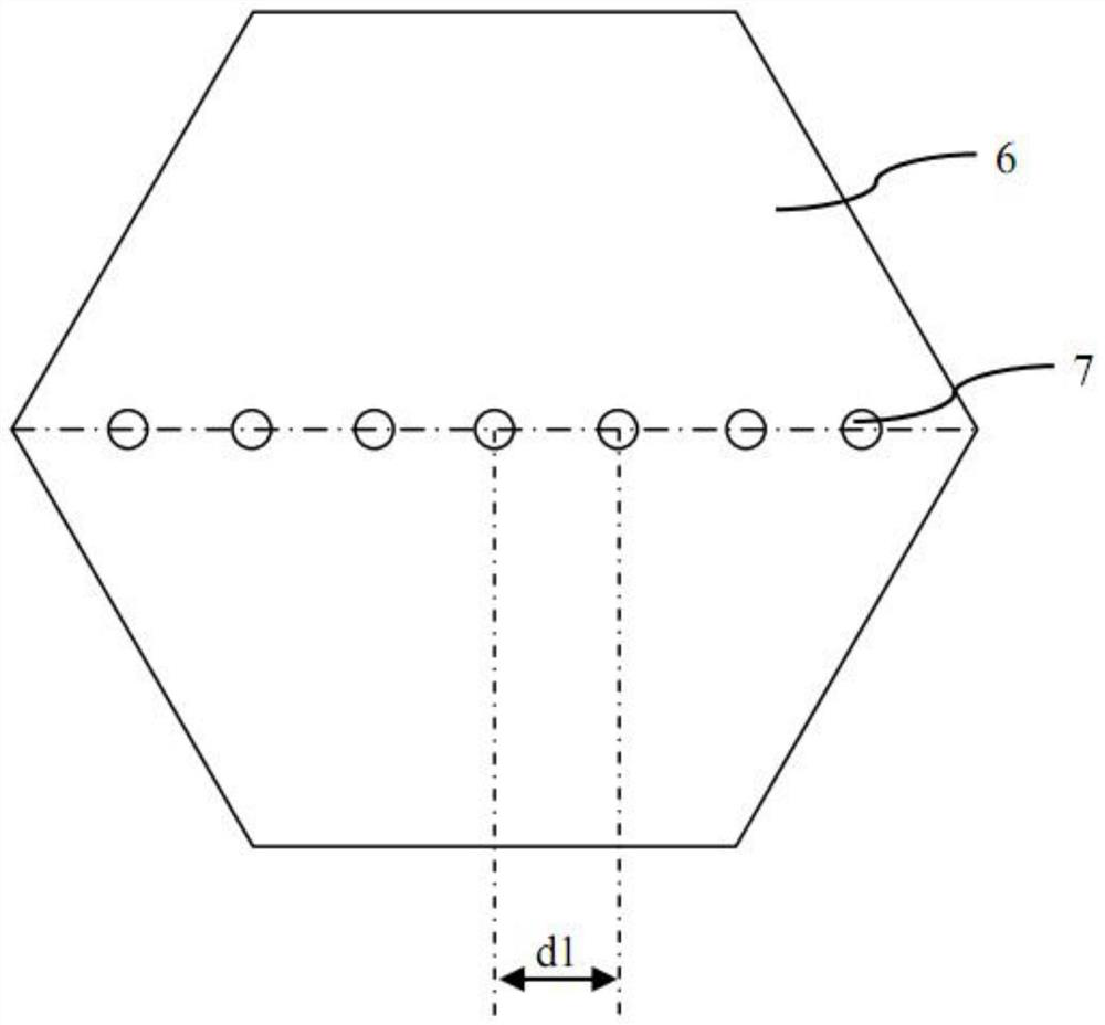
[0035] An optical system, which includes a first condenser lens 3, a fiber branch assembly 4, and a second condenser lens 10 arranged in sequence along the first optical axis direction; the fiber branch assembly 4 includes a beam splitter 5 and an optical fiber bundle assembly, The fiber bundle assembly is arranged in the extension direction of the first optical axis of the beam splitter 5; the fiber bundle assembly 4 includes a plurality of fiber bundles 7 and a hexagonal reflector 6, and the fiber bundles 7 are evenly distributed on the In the reflection cover 6, the reflection cover 6 is used t...


PUM


Abstract

The invention provides a computer control laser machining device and a machining method thereof. The computer control laser machining device can implement simultaneous cutting of multiple cutting channels and can also ensure the perpendicularity of the cutting channels and flexibly control the distance between the cutting channels. The computer control laser machining device can reduce cracks andfragments to the maximum extent, control energy of a first laser device and control the cutting speed. The computer control laser machining device achieves accurate control to prevent improper cuttingoperation through full computer control.

Description

technical field [0001] The invention relates to the field of semiconductor wafer cutting, in particular to a computer-controlled laser processing device and a processing method thereof. Background technique [0002] The cutting of silicon wafers or other semiconductor wafers often adopts mechanical cutting or laser cutting, and laser cutting has the beneficial effect of preventing the risk of fragments and cracks; however, existing laser cutting devices can only cut one dividing line at a time, or cut The spacing of multiple cutting lines is fixed, which is not conducive to the speed and flexibility of cutting; in addition, if the laser head or laser system is inclined in the vertical direction, that is, it is not perpendicular to the silicon wafer, then the cutting line Tilting can also occur, which can lead to failure of the cut piece. Contents of the invention [0003] Based on solving the above problems, the present invention provides a computer-controlled laser proce...

Claims


Application Information

Patent Timeline
Patent Type & Authority Patents(China)
IPC IPC(8): B23K26/38B23K26/067B23K26/70B23K26/064
CPCB23K26/064B23K26/0673B23K26/38B23K26/707
Inventor 董长娥
Owner ZIBO VOCATIONAL INST
Why Eureka
Eureka Blog
Learn More