Induction field intensity enhancement device and method for tip of electrostatic spinning spray head

A spinning nozzle and electrospinning technology, which is applied in textiles and papermaking, filament/thread forming, fiber processing, etc., can solve problems such as the tip of the nozzle, improve equipment safety and operation continuity, and reduce The effect of breakdown risk and simple method

Active Publication Date: 2019-03-19
QINGDAO UNIV OF SCI & TECH
View PDF4 Cites 4 Cited by
  • Summary
  • Abstract
  • Description
  • Claims
  • Application Information

AI Technical Summary

Problems solved by technology

[0004] At present, domestic and foreign research on the electric field intensity at the tip of the nozzle during the electrospinning process mostly focuses on the uniformity of the electric field intensity of multiple nozzles and increasing the voltage. Apparatus and method for controlling electric field strength

Method used


Image

  • Induction field intensity enhancement device and method for tip of electrostatic spinning spray head
  • Induction field intensity enhancement device and method for tip of electrostatic spinning spray head

Examples


Embodiment 1

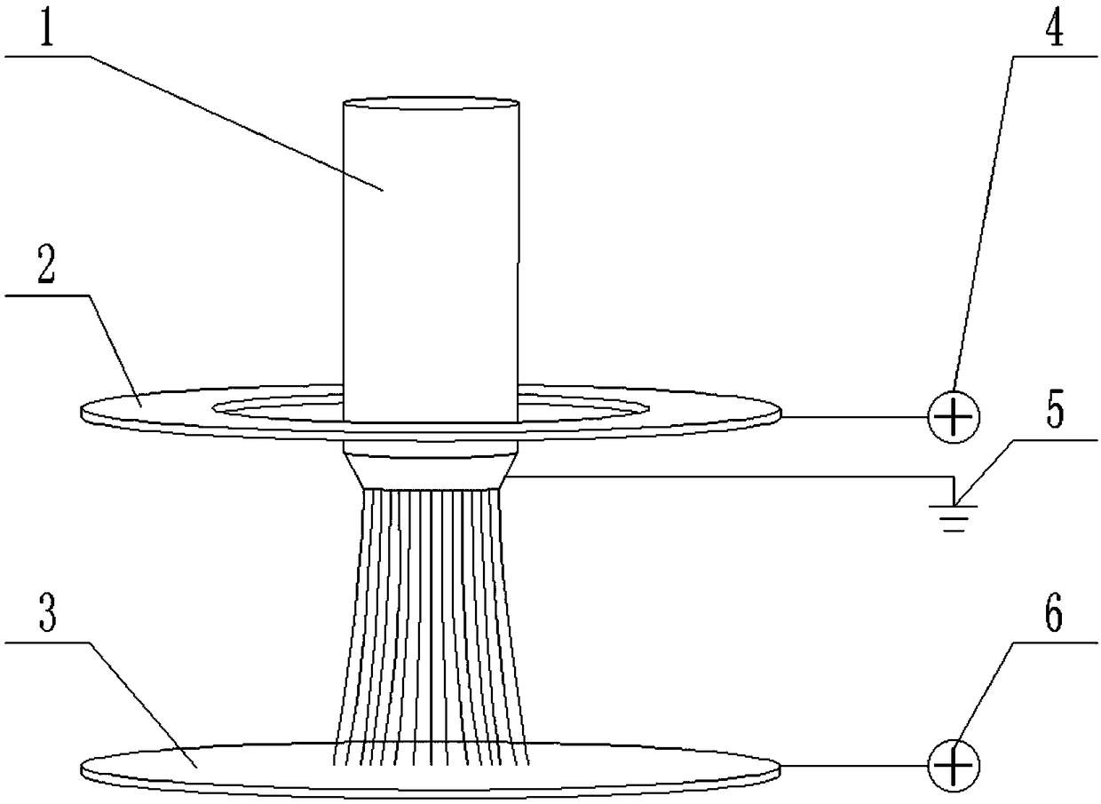
[0024] The schematic diagram of embodiment 1 is as figure 1 As shown, the spinning nozzle 1 is a cylindrical needle-free nozzle with a diameter of 30 mm, and the lower end is an annular cone tip, which is connected to the ground electrode 5 . The first electrode plate 2 is connected to the first high-voltage electrode 4. The first electrode plate 2 is a ring structure with an inner diameter of 60 mm, an outer diameter of 100 mm, and a thickness of 2 mm. The spinning nozzle 1 passes through the first electrode plate 2 and is coaxial. Placed, the distance between the lower surface of the first electrode plate 2 and the tip of the spinning nozzle 1 is 15mm. The second electrode plate 3 is connected to the second high-voltage electrode 6. The second electrode plate 3 is a circular structure with a diameter of 100 mm and a thickness of 2 mm. It is placed on the opposite side of the first electrode plate 2. The upper surface of the second electrode plate 3 is in contact with the spi...

Embodiment 2

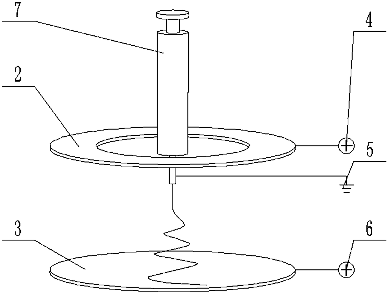
[0027] The schematic diagram of embodiment 2 is as figure 2 As shown, the spinning needle 7 is a hollow metal needle with free loading and unloading at the end of the syringe. The spinning needle 7 passes through the center hole of the first electrode plate 2 and is coaxially arranged with a distance of 10 mm. The rest of the configuration is the same as that of Embodiment 1. Use deionized water and polyvinyl alcohol (PVA) powder to stir and configure at 60°C, then cool to room temperature to obtain an 8% PVA solution, put it into the spinning needle 7, and under pressure, the solution is slowly extruded to the spinning needle. At the needle point of the silk needle 7, open the second high-voltage electrode 6, adjust the voltage to 40kV, produce a violently whipped spiral jet at the needle point of the spinning needle 7, open the first high-voltage electrode 4, and adjust its voltage to 20kV, The induction field strength at the tip of the spinning needle 7 is enhanced, the wh...


PUM


Abstract

The invention discloses an induction field intensity enhancement device and method for the tip of an electrostatic spinning spray head, and belongs to the field of electrostatic spinning. The induction field intensity enhancement device mainly comprises a spinning spray head, a first electrode plate, a second electrode plate, a first high-voltage electrode, a grounding electrode and a second high-voltage electrode, wherein the first electrode plate is perforated and penetrates through the spinning spray head, and is flush with the tip of the spinning spray head or is arranged at the same sideat a certain distance from the tip, the second electrode plate is arranged at the opposite side at a certain distance from the tip of the spinning spray head, the spinning spray head is connected withthe grounding electrode, the first electrode plate is connected with the first high-voltage electrode, the second electrode plate is connected with the second high-voltage electrode, two electrifiedelectrode plates make the spray head electrified through induction, formed electric fields are superposed, so that the induction field intensity of the tip of the electrostatic spinning spray head isenhanced, and it can be achieved that two weaker applied voltages are utilized, the induction field intensity of the tip of the spray head is increased while the breakdown risk is reduced, thereby achieving the purposes of further reducing the fiber diameter and increasing the jet flow number of the spinning spray head.

Description

technical field [0001] The invention relates to a device and method for enhancing the induction field strength at the tip of an electrospinning nozzle, belonging to the field of electrospinning. Background technique [0002] Electrospinning is a special manufacturing process in which a polymer melt or solution is polarized or charged under the action of a high-voltage electric field to form a jet, and is accompanied by cooling or solvent volatilization to form ultrafine fibers. [0003] The key technical feature of electrospinning is to form a high-voltage electric field between the nozzle and the receiving plate. The specific operation method is to place the nozzle and the receiving plate in the up and down or left and right directions, and the nozzle is grounded, the receiving plate is connected to the high-voltage electrode or the receiving plate is grounded. , The nozzle is connected to the high-voltage electrode. Increasing the output voltage of the high-voltage electr...

Claims


Application Information

Patent Timeline
IPC IPC(8): D01D5/00
CPCD01D5/0069D01D5/0092
Inventor 陈宏波汪传生韩雯雯杨卫民田晓龙
Owner QINGDAO UNIV OF SCI & TECH
Why Eureka
Try Eureka