Heat pump control method for dehumidification and drying
What is AI technical title?
AI technical title is built by Patsnap AI team. It summarizes the technical point description of the patent document.
A control method and heat pump technology, applied in drying, heat pump, dryer, etc., can solve the problem of low temperature dehumidification of materials
Active Publication Date: 2019-03-19
JIANGSU TENESUN ELECTRICAL APPLIANCE
View PDF5 Cites 17 Cited by
Summary
Abstract
Description
Claims
Application Information
AI Technical Summary
This helps you quickly interpret patents by identifying the three key elements:
Problems solved by technology
Method used
Benefits of technology
Problems solved by technology
[0006] The invention application with the application number 201610094280.6 discloses a drying dehumidifier, including a compressor, an indoor condenser, an outdoor evaporator, a first throttle valve, an outdoor heat exchanger and a control system. The dehumidification circulation pipeline and the low-temperature dehumidification circulation pipeline, the controller controls the circulation of the refrigerant in the corresponding circulation pipeline, and can heat up or cool down the dehumidification of the material, thereby overcoming the drying and dehumidification heat pump unit in the prior art that only has the function of heating and dehumidification Mode, but not the defect of low temperature dehumidification of materials
Method used
Image
Click on the blue label to locate the original text in one second.
Reading with bidirectional positioning of images and text.
Examples
Embodiment 1
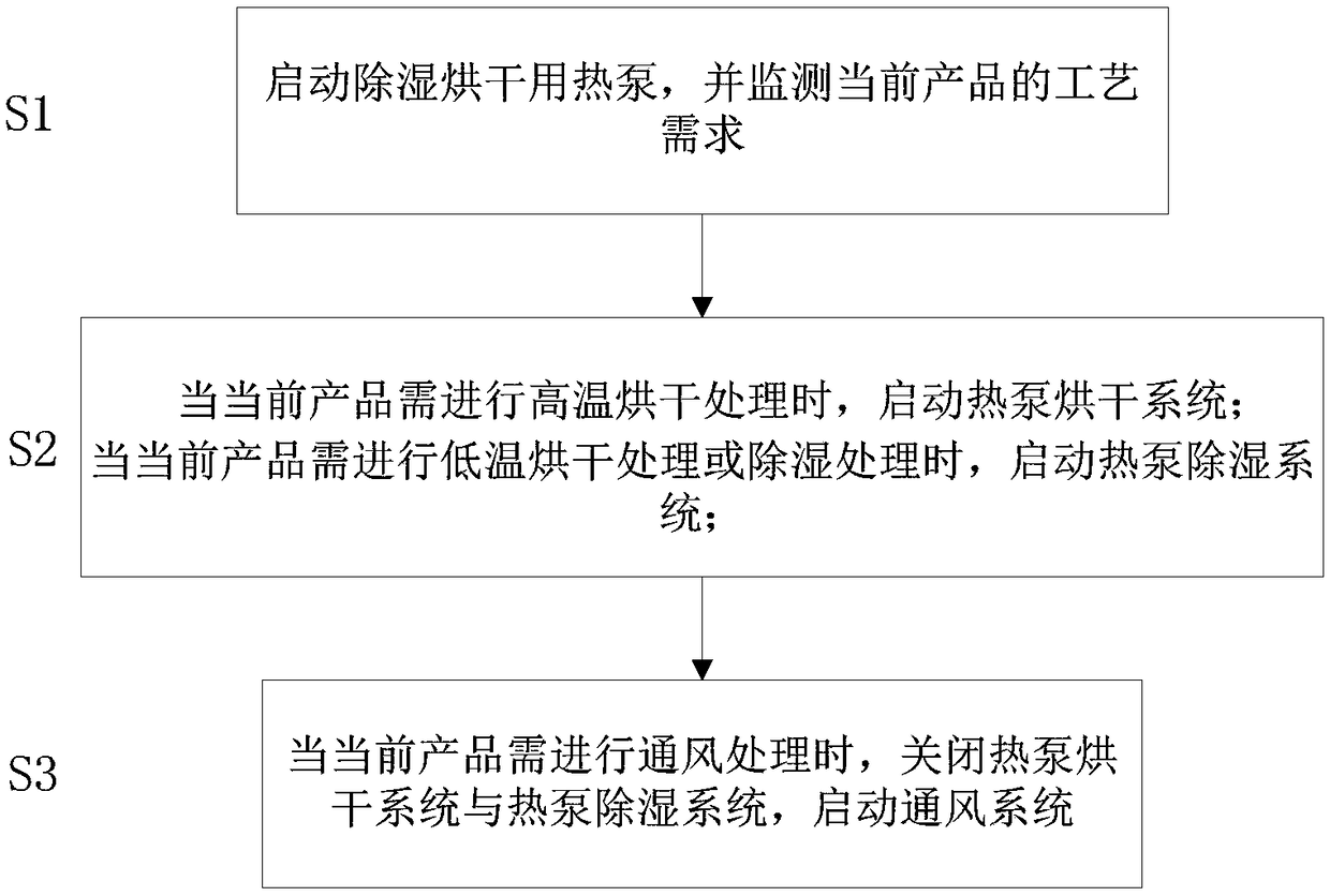
[0221] The control in this embodiment provides switching between the three modes of the product: baking mode, dehumidification mode and ventilation mode;
[0222] The closed refrigerant heat exchange circuit that constitutes the baking mode is composed of compressors, four-way valves, air supply heating condensers, liquid receivers, outdoor evaporators, four-way valves, and vapor-liquid separators connected in sequence.
[0223] The closed refrigerant heat exchange circuit that constitutes the dehumidification mode is composed of a compressor, a four-way valve, a supply air heating condenser, a liquid receiver, a return air evaporator, a four-way valve, and a vapor-liquid separator connected in sequence.
[0224] The hot air supply channel that constitutes the baking mode or dehumidification mode is composed of a supply air heating condenser, a supply fan, and a drying room connected by pipelines in sequence.
[0225] Set the return air setting after the air supply to cooperat...
Embodiment 2
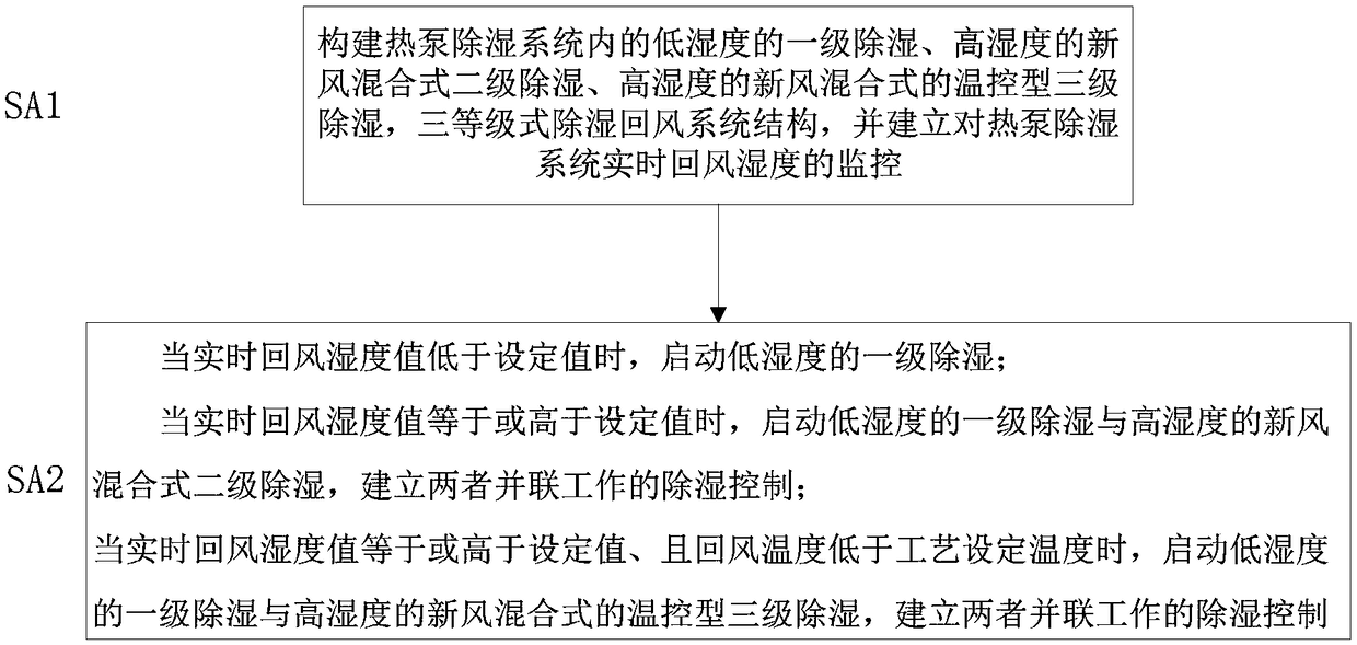
[0230] The control in this embodiment is based on the dehumidification mode, and further establishes three levels of dehumidification control in the dehumidification mode according to the humidity of the return air, which are: Ⅰ. Low humidity level 1 dehumidification; Ⅱ. High humidityfresh airHybrid two-stage dehumidification; Ⅲ. High-humidity fresh air hybrid temperature-controlled three-stage dehumidification.
[0231] When the humidity of the return air is lower than the set value of the process, the low-humidity first-stage dehumidification is started, and the closed-type dehumidification composed of the drying room, the first primary filter, the return air evaporator, and the supply air heating condenser connected by pipelines in sequence Circulation loop, forming a return air dehumidification channel for primary dehumidification;
[0232] When the humidity of the return air is higher than the set value of the process, the high-temperature fresh air mixed-type secondary...
Embodiment 3
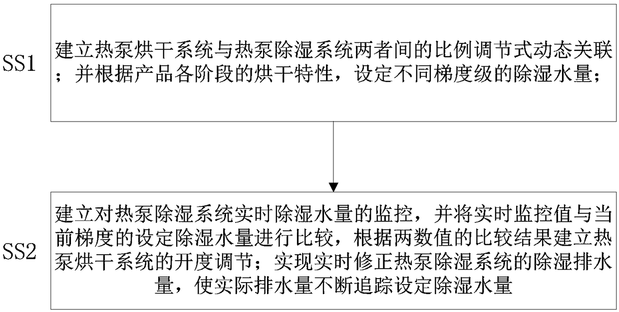
[0235] The control in this embodiment is based on the dehumidification mode, and further establishes a closed-loop adaptive dynamic dehumidification adjustment control system based on the baking mode and dehumidification mode according to the dehumidification displacement;
[0236] The baking mode is composed of a first heating unit and an air supply unit;
[0237] The dehumidification mode is composed of a second heating unit, an air supply unit and a return air dehumidification unit;
[0238] According to the dehumidification and drainage volume, a closed-loop self-adaptive dynamic dehumidification adjustment control system composed of the ratio adjustment between the first heating unit and the second heating unit is established;
[0239] The first heating unit is composed of a sequentially connected compressor, four-way valve, air supply heating condenser, liquid receiver, outdoor evaporator, four-way valve, and vapor-liquid separator;
[0240] The second heating unit is c...
PUM
Abstract
The invention relates to a heat pump control method for dehumidification and drying. A heat pumpdryingsystem, a heat pump dehumidification system and a ventilation system are established according to three factors of drying, dehumidification and ventilation, and according to the process requirements of current products, the heat pump control method for dehumidification and drying based on the heat pump drying system, the heat pump dehumidification system and the ventilation system is established. The heat pump control method for dehumidification and drying includes the steps that air sourcemulti-dimensional treatment type dehumidification and drying control is established, and according to the requirements of different process working conditions, air from a drying room can be simultaneously dehumidified and heated to meet the requirement of dehumidification; heat can be also absorbed from the external environment space, the heat is transferred to the drying room, and the requirementof the high temperature environment is met; and when the humidity of a unit is high, dehumidification and fresh air entering are conducted, total heat recovery is conducted on fresh air and dehumidification , and the heat loss during dehumidification is effectively avoided. Not only is the requirement of dehumidification under the low temperature working condition met, but also the requirements of dehumidification and drying at high temperature are ensured, the drying effect of the products is ensured, and the operating costs of the products are reduced.
Description
technical field [0001] The invention belongs to the field of hot air drying, and in particular relates to a heat pump control method for dehumidification and drying. Background technique [0002] At present, there are more and more places that need hot air drying in the market, such as tobacco drying, grain drying, medicinal materials drying, fruit and vegetable drying and other drying places. Coal furnaces, gas furnaces and electric furnaces are mainly used for drying. Coal and gas are non-renewable strategic energy sources, which are not the direction of national promotion. Electric furnaces are not suitable for mass promotion because of their high energy consumption and high operating costs. Due to the many reasons mentioned above, heat pump dryers are now gradually being accepted by the market because of their many advantages such as energy saving, environmental protection, and high drying quality. There are two main types of drying heat pumps on the market, one is hot ...
Claims
Application Information
Patent Timeline
Application Date:The date an application was filed.
Publication Date:The date a patent or application was officially published.
First Publication Date:The earliest publication date of a patent with the same application number.
Issue Date:Publication date of the patent grant document.
PCT Entry Date:The Entry date of PCT National Phase.
Estimated Expiry Date:The statutory expiry date of a patent right according to the Patent Law, and it is the longest term of protection that the patent right can achieve without the termination of the patent right due to other reasons(Term extension factor has been taken into account ).
Invalid Date:Actual expiry date is based on effective date or publication date of legal transaction data of invalid patent.

