
Portable fault indicator detection equipment

A technology of fault indicator and testing equipment, applied in the direction of instruments, measuring devices, measuring electrical variables, etc., can solve the problems of the overall weight of the equipment, inconvenient to use, etc., and achieve the effects of reduced self-weight, easy operation, and convenient and rapid testing.

Inactive Publication Date: 2019-03-19
STATE GRID HEBEI ELECTRIC POWER CO LTD +1
View PDF9 Cites 2 Cited by
  • Summary
  • Abstract
  • Description
  • Claims
  • Application Information

AI Technical Summary

Problems solved by technology

[0004] However, the existing fault indicator detection equipment has the following disadvantages: 1. It needs to be controlled by an external computer to output; 2. When the output current is greater than 100A, an external coil is required; 3. The overall weight of the equipment is relatively heavy, and the on-site test needs to carry a lot accessories, very inconvenient to use

Method used


Image

  • Portable fault indicator detection equipment
  • Portable fault indicator detection equipment

Examples


Embodiment Construction

[0023] In order to make the object, technical scheme and advantages of the present invention clearer, the following in conjunction with the attached figure 1 and specific examples to clearly and completely describe the invention.

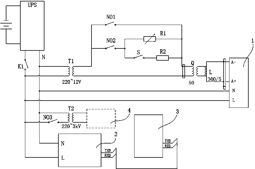
[0024] Such as figure 1 As shown, the present embodiment relates to a portable fault indicator detection device, which includes a UPS power supply, an ammeter 1, a single-chip microcomputer 2, a touch screen 3 and an internal control circuit; the internal control circuit includes a transformer T1, a transformer T2, a switch NO1, switch NO3, transformer Q, induction coil L and current regulation branch; the current regulation branch includes switch NO2, current range switch S2, adjustable resistor R1 and resistor R2; the current range switch S2 and The resistor R2 is connected in parallel with the adjustable resistor R1 after being connected in series, and the circuit connected in parallel is connected in series with the switch NO2;

[0025] The tw...


PUM


Abstract

The invention discloses portable fault indicator detection equipment, belonging to detection equipment. The portable fault indicator detection equipment comprises a UPS power supply, an ammeter, a singlechip, a touch screen and an internal control circuit, wherein the internal control circuit comprises a transformer T1, a transformer T2, a switch NO1, a switch NO3, a mutual inductor Q, an induction coil L and a current regulating branch; the current regulating branch circuit comprises a switch NO2, a current measuring range switching switch S2, an adjustable resistor R1 and a resistor R2; theammeter is connected with the UPS power supply; the switch NO3 and the transformer T2 are connected in series between a tested fault indicator and a power supply output end of the UPS power supply; and the singlechip is connected with the touch screen. By the adoption of the portable fault indicator detection equipment, voltage and current waveforms of various faults can be simulated, a pluralityof faults and anti-misoperation functions can be tested; the UPS power supply is provided so that a fault indicator test can be carried out in a field environment with power supply or power failure; and circuit faults are simulated in a state sequence mode of voltage and current to test whether the fault indicator can work normally or not, the fault indicator is guaranteed to be in a reset state after the test is finished, and a network can be hung in time.

Description

technical field [0001] The invention belongs to the field of detection equipment, and in particular relates to a portable fault indicator detection equipment. Background technique [0002] Fault indicators are generally installed on overhead lines, overhead cables or buried cables, and switchgear busbars, so it detects voltage by detecting the potential gradient of the electric field in space, and detects line current by electromagnetic induction. [0003] The fault indicator tester performs function test and performance evaluation on the fault indicator by simulating the current and voltage characteristics of the faulty branch and the non-faulty branch in the case of a typical short circuit of the feeder line and a single-phase ground fault. The effective value of voltage and current can be set at any point in time, and the voltage and current can be set to change slowly, suddenly rise, and suddenly drop within a period of time. Users can refer to the recorded wave data of ...

Claims


Application Information

Patent Timeline
Patent Type & Authority Applications(China)
IPC IPC(8): G01R35/00
CPCG01R35/00
Inventor 耿亮苑波任硕付伟徐亚兵常永杰张郁王得志王代远刘玉峰申政刘国平董江涛刘保安
Owner STATE GRID HEBEI ELECTRIC POWER CO LTD
Learn More