Data center heat dissipation system with direct connection between loop heat pipe and refrigeration cycle pipe

A refrigeration cycle, loop heat pipe technology, applied in cooling/ventilation/heating renovation, electrical components, electrical equipment structural parts, etc., can solve problems such as loud noise, corroded components, liquid leakage circuits, etc., to reduce energy consumption and temperature difference loss, reduce start-up time and power, reduce energy consumption and noise effect

Active Publication Date: 2019-03-19
CHINA ACAD OF AEROSPACE AERODYNAMICS
View PDF5 Cites 4 Cited by
  • Summary
  • Abstract
  • Description
  • Claims
  • Application Information

AI Technical Summary

Problems solved by technology

Traditional computer room heat dissipation systems mainly include air cooling and liquid cooling. The air-cooled computer room cooling system mainly relies on the computer room air conditioner to reduce the indoor air temperature in the computer room, and then organizes the airflow through the built-in fans and channels in the server cabinet to make the indoor cold air enter the cabinet. Heat exchange with the server, the heat dissipation technology is relatively mature, but it consumes a lot of energy to organize the airflow and increase the heat exchange temperature difference between the server and the cold air, the noise is large, and it is easy to cause local overheating and cause downtime; the development of liquid-cooled computer room heat dissipation system is relatively relatively At present, there are various forms such as water-cooled heat dissipation at the end of the organic room air conditioner combination, immersion heat dissipation, etc., but they all face technical problems such as liquid leakage that can easily cause circuit failures and corrode components.

Method used


Image

  • Data center heat dissipation system with direct connection between loop heat pipe and refrigeration cycle pipe
  • Data center heat dissipation system with direct connection between loop heat pipe and refrigeration cycle pipe

Examples


Embodiment Construction

[0036] The present invention will be described in detail below with reference to the accompanying drawings and embodiments.

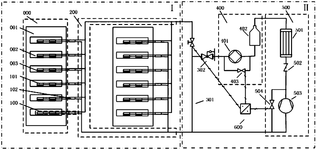
[0037] The invention provides a data center heat dissipation system in which a loop heat pipe and a refrigeration cycle pipe are directly connected. , the heat pipe has the advantages of high heat conduction efficiency and does not consume additional energy to provide the working medium circulation power; the cabinet to the outdoor is realized by the refrigerant circulation unit.

[0038] figure 1 A schematic diagram of the device structure principle according to an embodiment of the present invention is given. like figure 1 As shown, in this embodiment, the computer room unit includes two sets of server units, wherein one set of server units includes a rack 001 and one or more servers 002 installed on the rack, and the server 002 may include one or more chips 003. The present invention will be described below by taking the set of servers as an exam...


PUM


Abstract

The invention relates to a data center heat dissipation system with direct connection between a loop heat pipe and a refrigeration cycle pipe. The system comprises a loop heat pipe unit, a circulatingworking-medium fast joint unit, and a refrigerant circulation unit. The loop heat pipe unit includes a gas pipe, a liquid pipe, an evaporation end and a condensation end; liquid generated by condensation in the condensation end flows through the liquid pipe to the evaporation end; the evaporation end is adhered to a chip in a server; and heat generated by the chip in the server heats the liquid to generate gas by evaporation and the gas returns to the condensation end along the gas pipe. The condensation end is connected to a refrigeration cycle pipe of the refrigerant circulation unit through the circulating working-medium fast joint unit; the circulating working medium transmits the heat generated by the condensation end of the loop heat pipe unit to a condenser of the refrigerant circulation unit; and the heat is exchanged to the outdoor space by the condenser. Because of direct connection between the heat pipe and the refrigeration cycle pipe, the heat exchange link and the temperature difference loss from the chip to the refrigeration circulation are reduced; and the energy consumption and noises caused by the traditional machine room heat dissipation technology are reduced.

Description

technical field [0001] The invention relates to a heat dissipation system of a data center in which a loop heat pipe and a refrigeration circulation pipe are directly connected, and belongs to the technical fields of heat dissipation in a computer room, heat pipe technology and refrigeration device. Background technique [0002] With the improvement of the computing power requirements of the data room and the efficient miniaturization of chips, modern data centers have more and more stringent requirements for the cooling of the computer room. The PUE index of the existing data room is about 1.6, that is, the ratio of the server running power consumption in the data room to the cooling power consumption of the data room is about 10:6. The traditional computer room cooling system mainly includes air cooling and liquid cooling. The air-cooled computer room cooling system mainly relies on the computer room air conditioner to reduce the indoor air temperature in the computer room...

Claims


Application Information

Patent Timeline
Patent Type & Authority Applications(China)
IPC IPC(8): H05K7/20
CPCH05K7/20809H05K7/20836
Inventor 段江菲薛志虎陈思员罗晓光曲伟俞继军艾邦成
Owner CHINA ACAD OF AEROSPACE AERODYNAMICS
Why Eureka
Try Eureka