
PET (Positron Emission Tomography) annular detection imaging system based on scintillation fibers

A technology of scintillation optical fiber and imaging system, which is used in computer tomography scanners, echo tomography and other directions, can solve the problems of inability to obtain the depth and position information of reactants, low imaging resolution, and limited decoding accuracy. Simple and intuitive, high resolution, and the effect of reducing the effect of errors

Active Publication Date: 2019-03-22
HUAZHONG UNIV OF SCI & TECH +1
View PDF8 Cites 6 Cited by
  • Summary
  • Abstract
  • Description
  • Claims
  • Application Information

AI Technical Summary

Problems solved by technology

[0004] Traditional crystal array coupled sensors are limited by technology, cost, etc. When the crystal size is cut below 1mm, the cost will increase significantly, and the decoding accuracy is limited by the crystal size
At the same time, the existing multiple detector modules are combined in the circumferential direction to form a single-ring detector structure. The axial expansion and splicing of the single-ring detector structure can expand the axial length of the ring scintillation fiber PET imaging system according to actual needs, but this In the way of splicing, there will be missed detection and missed detection at the splicing place, resulting in low detection accuracy and low imaging resolution. Secondly, the traditional PET imaging system unobtrusively adopts the arrangement of one end of the scintillating optical fiber equipped with a light sensor, and this This arrangement cannot obtain more accurate depth position information of reactants

Method used


Image

  • PET (Positron Emission Tomography) annular detection imaging system based on scintillation fibers
  • PET (Positron Emission Tomography) annular detection imaging system based on scintillation fibers
  • PET (Positron Emission Tomography) annular detection imaging system based on scintillation fibers

Examples


Embodiment Construction

[0033] In order to make the object, technical solution and advantages of the present invention clearer, the present invention will be further described in detail below in conjunction with the accompanying drawings and embodiments. It should be understood that the specific embodiments described here are only used to explain the present invention, not to limit the present invention. In addition, the technical features involved in the various embodiments of the present invention described below can be combined with each other as long as they do not constitute a conflict with each other.

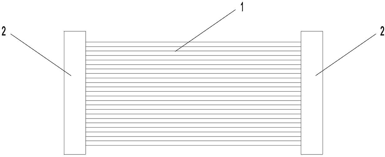
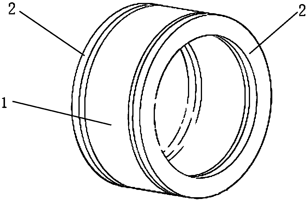
[0034] as attached figure 1 and figure 2 As shown, a PET ring detection imaging system based on scintillation fiber optics is provided, including a plurality of detector modules connected sequentially along its central axis, wherein the detector modules include scintillation fiber optic units and optical The sensor unit; the scintillation fiber unit is composed of a plurality of scintillation...


PUM


Abstract

The invention belongs to the technical field of electron emission imaging, and discloses a PET (Positron Emission Tomography) annular detection imaging system based on scintillation fibers. The systemcomprises a plurality of detector modules which are sequentially connected along a central axis, wherein each of the detector modules consists of a scintillation fiber unit and a photosensor unit; the photosensor units are symmetrically arranged at two ends of the integral scintillation fiber unit; a plurality of photosensors are arranged on the photosensor unit at each end; and each photosensoris respectively correspondingly coupled with a plurality of scintillation fibers in the scintillation fiber unit. According to the system, the error influence caused by energy attenuation on positioning is effectively reduced, the reaction positions of the scintillation optical fibers are easily judged, missed detection cannot be caused due to splicing of a plurality of the detector modules, and detection information is more accurate and comprehensive, so that the PET annular detection imaging system has the characteristics of high efficiency, high sensitivity, high imaging resolution and morecompact devices.

Description

technical field [0001] The invention belongs to the technical field of electron emission imaging, and more particularly relates to a PET ring detection imaging system based on scintillation optical fiber. Background technique [0002] The full name of PET is positron emission tomography PET (positron emission tomography PET), which is an imaging device that reflects the gene, molecule, metabolism and functional state of the disease. It uses positron nuclide-labeled glucose and other human metabolites as imaging agents, and reflects its metabolic changes through the uptake of imaging agents by lesions, thereby providing clinical biological metabolism information of diseases. PET uses positron nuclide as a tracer. Through the uptake of the tracer at the lesion site to understand the functional and metabolic state of the lesion, it can macroscopically display the pathophysiological characteristics of the function and metabolism of various organs in the whole body, and it is eas...

Claims


Application Information

Patent Timeline
Patent Type & Authority Applications(China)
IPC IPC(8): A61B6/03
CPCA61B6/037
Inventor 许剑锋谢杨泽原东升彭辉谢思维彭旗宇
Owner HUAZHONG UNIV OF SCI & TECH
Learn More