Tinned wire spot welding device and annular capacitor production equipment

A technology of spot welding device and tinned wire, which is applied to tin feeding device, welding equipment, capacitors, etc., can solve the problems of long cylindrical capacitors being easily disordered in vertical feeding, low welding quality, and interference of dust and impurities. Achieve the effect of high qualified rate of finished products, firm and reliable welding, and improved welding accuracy

Inactive Publication Date: 2019-03-22
张玉仙
View PDF7 Cites 2 Cited by
  • Summary
  • Abstract
  • Description
  • Claims
  • Application Information

AI Technical Summary

Problems solved by technology

The shortcomings of the existing production equipment are: 1. The vertical feeding of long cylindrical capacitors is easy to be confused; 2. The turntable works continuously, and the accuracy is low due to error accumulation; 3. The connection between the lead wire and the capacitor is not reliable, usually directly through soldering The connection is not firm in this way; 4. The lack of positioning in the vertical direction of the capacitor leads to low welding accuracy, and there is interference from dust and impurities during welding; 5. The contact between the lead wire and the capacitor is point contact, which is difficult to weld, and the welding quality is not high

Method used


Image

  • Tinned wire spot welding device and annular capacitor production equipment
  • Tinned wire spot welding device and annular capacitor production equipment
  • Tinned wire spot welding device and annular capacitor production equipment

Examples


Embodiment Construction

[0035] The present invention will be further described below in conjunction with the accompanying drawings and embodiments.

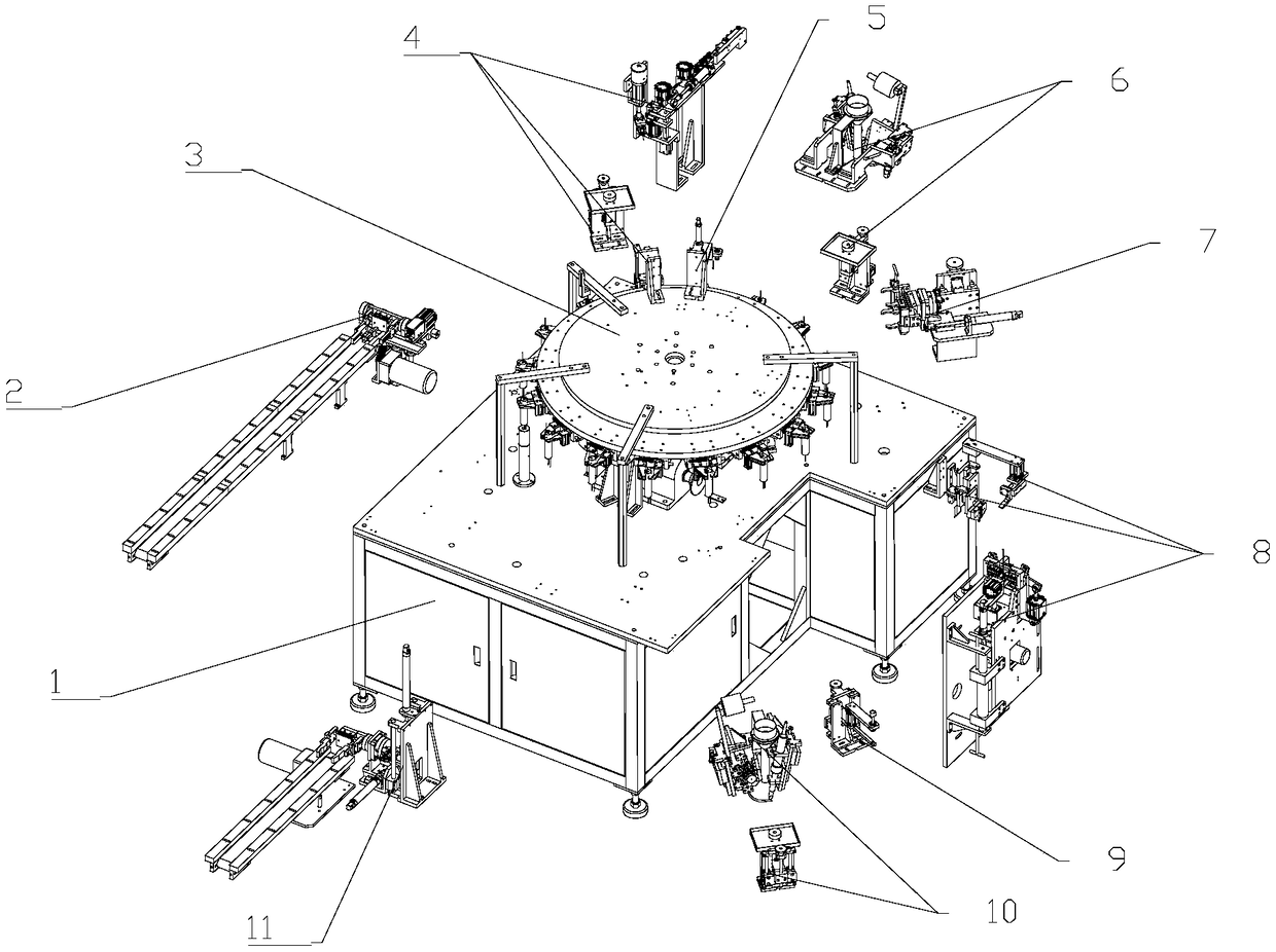
[0036] Such as figure 1 As shown, the circular capacitor production equipment includes a frame 1 and a capacitor feeding device 2 installed on the frame 1, a turntable transfer device 3, a tinning line spot welding device 4, a tinning line detection device 5, a tinning line Wire welding device 6 , capacitor flipping device 7 , colloidal line spot welding device 8 , colloidal line detection device 9 , colloidal line welding device 10 and finished product blanking device 11 .

[0037] The turntable transfer device 3 is installed in the central part of the frame 1 to drive the workpiece to rotate; along the direction of material movement on the turntable transfer device 3, the capacitor feeding device 2, the tinned line spot welding device 4, and the tinned line detection Device 5, tinned wire welding device 6, capacitor flipping device 7, colloidal wire ...


PUM


Abstract

The invention relates to the field of circuit element manufacturing. A tinned wire spot welding device comprises a tinned wire feeding mechanism, a clamping and carrying mechanism, a first adjustablejacking limiting assembly and a first alternating current point welding assembly. The tinned wire spot welding device has the advantages that welding of a tinned wire and a capacitor is firm and reliable, dislocation of the a tinned wire and the capacitor during welding is prevented through point welding pretreatment, and the welding precision is improved.

Description

technical field [0001] The invention relates to the field of circuit element manufacturing, in particular to welding equipment for circular cylindrical capacitors. Background technique [0002] Compared with ordinary capacitors, because it is directly installed on the metal panel, the cylindrical capacitor has smaller grounding inductance and almost no influence of lead inductance. In addition, its input and output terminals are isolated by metal plates, which eliminates high frequency Coupling, these two characteristics determine that the cylindrical capacitor has a filtering effect close to the ideal capacitor, and the cylindrical capacitor is composed of a capacitor body and wiring. The shortcomings of the existing production equipment are: 1. The vertical feeding of long cylindrical capacitors is easy to be confused; 2. The turntable works continuously, and the accuracy is low due to error accumulation; 3. The connection between the lead wire and the capacitor is not rel...

Claims


Application Information

Patent Timeline
Patent Type & Authority Applications(China)
IPC IPC(8): B23K3/06B23K3/08B23P23/04H01G13/00H01R43/28
CPCB23K3/0607B23K3/08B23P23/04H01G13/006H01R43/28
Inventor 张玉仙张青华
Owner 张玉仙
Why Eureka
Try Eureka