
Oily sewage treatment system

A sewage treatment system and oil technology, applied in water/sewage multi-stage treatment, water/sludge/sewage treatment, mining wastewater treatment, etc., can solve the problem of exceeding separation capacity, excessive oil content in production water, and increased gas phase flow And other issues

Pending Publication Date: 2019-03-22
中石化石油工程技术服务有限公司 +2
View PDF7 Cites 0 Cited by
  • Summary
  • Abstract
  • Description
  • Claims
  • Application Information

AI Technical Summary

Problems solved by technology

[0004] As oilfield exploitation enters the middle stage, the downhole pressure decreases, the produced product and production operation pressure decrease, and the gas phase flow rate increases. The emulsification phenomenon caused by the heat exchange phase change and pipeline transmission process is more serious, which exceeds the existing technology and equipment. Separation ability, resulting in the oil content of the purified production water discharged from the production water transmission line exceeding the standard

Method used


Image

  • Oily sewage treatment system
  • Oily sewage treatment system
  • Oily sewage treatment system

Examples


Embodiment Construction

[0046] The drawings illustrate embodiments of the invention and it is to be understood that the disclosed embodiments are merely examples of the invention, which may be embodied in various forms; therefore, specific details disclosed herein should not be construed as limiting, but rather The claims are presented merely as a basis and as a representative basis for teaching one of ordinary skill in the art to variously practice the invention.

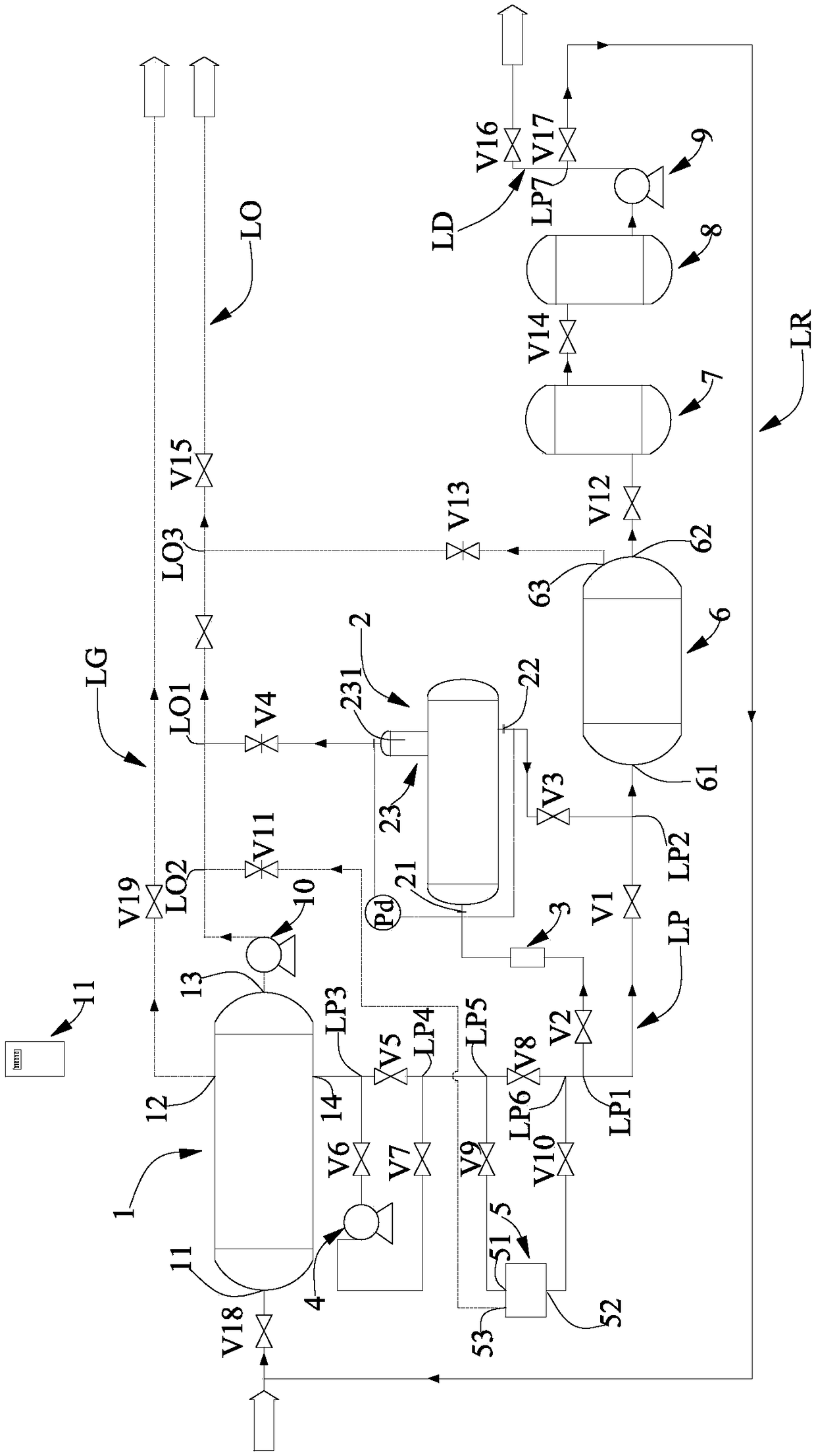
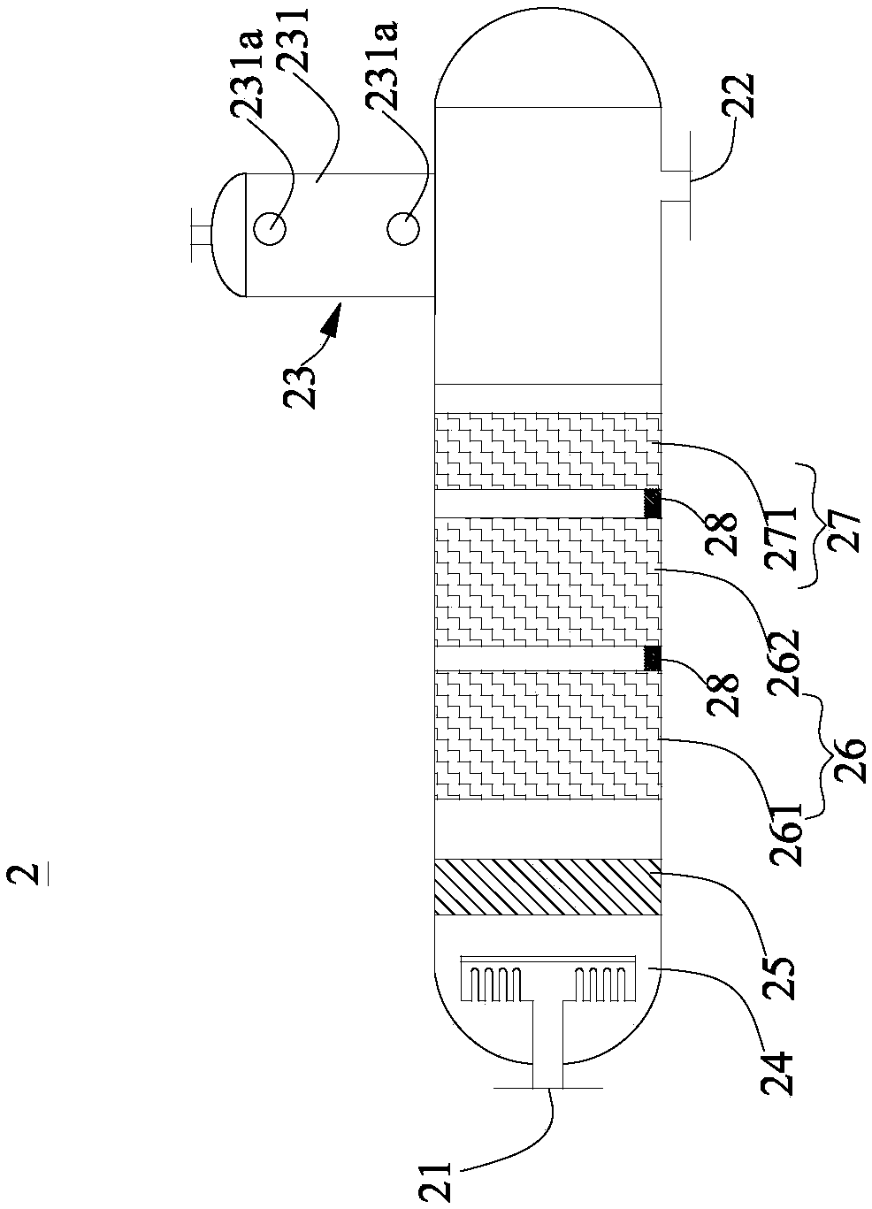
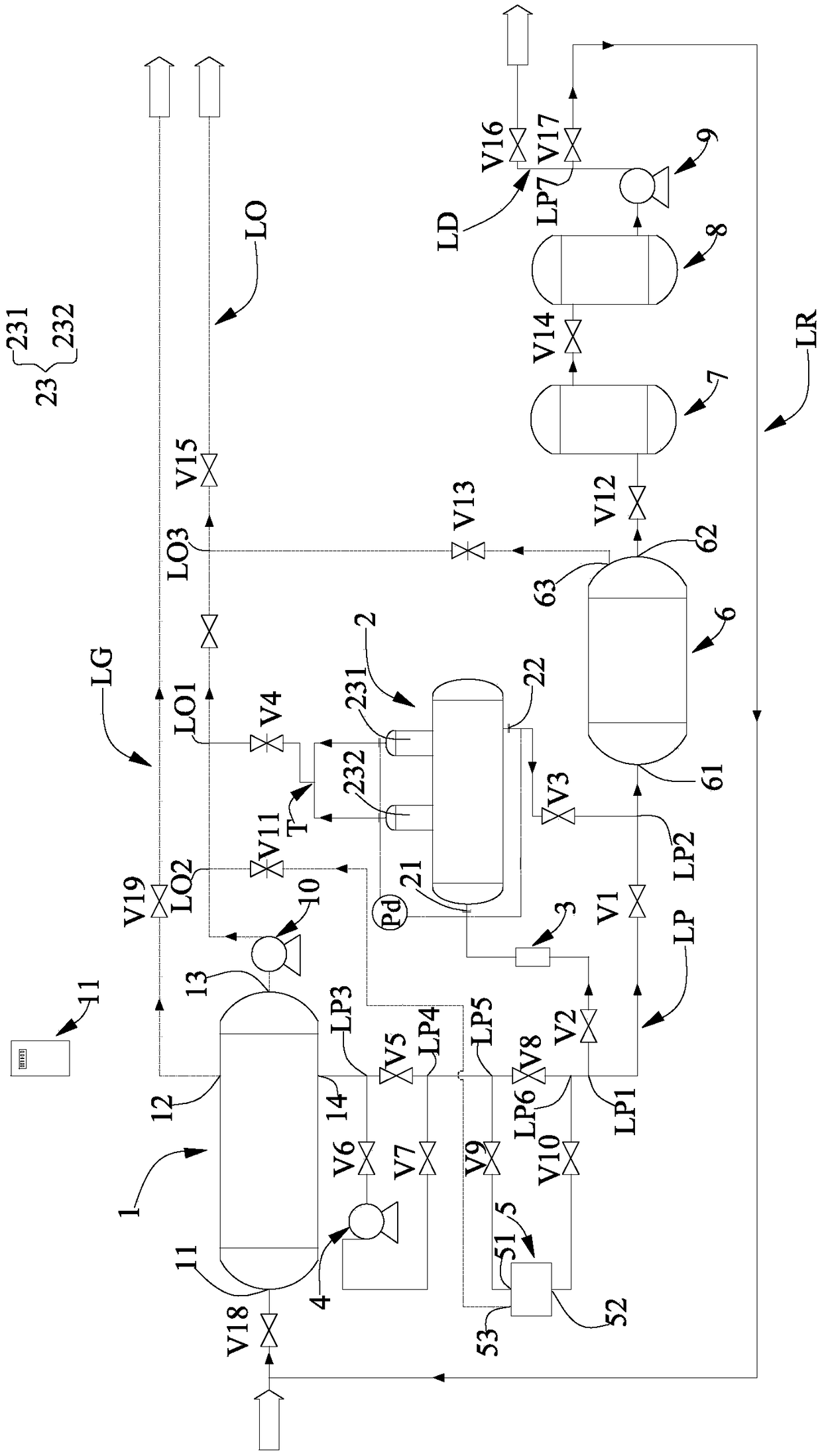
[0047] figure 1 is a schematic diagram of the first embodiment of the oily sewage treatment system according to the present invention. figure 2 Yes figure 1 Schematic diagram of the coalescence degreasing unit of the oily wastewater treatment system. image 3 is a schematic diagram of the second embodiment of the oily sewage treatment system according to the present invention. Figure 4 Yes image 3 Schematic diagram of the coalescence degreasing unit of the oily wastewater treatment system.

[0048] refer to figure 1 and figure ...


PUM

PropertyMeasurementUnit
voidageaaaaaaaaaa
particle diameteraaaaaaaaaa
separationaaaaaaaaaa

Abstract

The invention provides an oily sewage treatment system. The oily sewage treatment system comprises a production separator, an air conveying line, an oil conveying line, a production water conveying line and a coalescence oil removal device, wherein the oil conveying line is provided with a first connecting point, the production water conveying line is provided with a first access point and a second access point, and a first control valve is arranged between the first access point and the second access point; the coalescence oil removal device is arranged between the first access point and thesecond access point in a bypass way, and is provided with an inlet, a water outlet and an oil collection bag; a distributor, a flow arrangement device, a coalescence separation module, and a reinforced settlement module are arranged in the coalescence oil removal device along the flowing direction of the production water; a second control valve is connected between the inlet of the coalescence oilremoval device and the first access point of the production water conveying line; a third control valve is connected between the water outlet of the coalescence oil removal device and the second access point of the production water conveying line; a fourth control valve is connected between the oil collection bag of the coalescence oil removal device and the first connecting point of the oil conveying line.

Description

technical field [0001] The invention relates to the field of sewage treatment, in particular to an oily sewage treatment system. Background technique [0002] The incoming fluid from the downhole production manifold in land oilfields is a three-phase mixture of water, oil and gas at high temperature and high pressure. The oil is discharged to the oil recovery tank, the gas is sent to the heat exchanger, and the separated production water enters the buffer tank after deoiling treatment, and then is pumped back to the production liquid header, and the oil in the production water is discharged to the production liquid header. The content must meet the corresponding environmental standards. [0003] Since the produced product undergoes severe emulsification during the process of phase change during cooling by the heat exchanger, water-in-oil and oil-in-water emulsions are formed, while the separation of oil and water in the production separator is simply gravity Settling or en...

Claims


Application Information

Patent Timeline
Patent Type & Authority Applications(China)
IPC IPC(8): C02F9/02B01D17/025B01D17/04C02F103/10
CPCB01D17/0208B01D17/045C02F9/00C02F2001/007C02F2103/10C02F1/001C02F1/40
Inventor 刘海丽代品一李清方杨强于惠娟孙盖南郭长会卢浩
Owner 中石化石油工程技术服务有限公司
Learn More