Novel precisely adjustable large-span steel pipe truss unloading bracket and using method thereof
A steel pipe truss and large-span technology, applied in the processing of building materials, preparation of building components on site, manufacturing tools, etc., can solve the problems that hinder the development of jack unloading methods, require high operators, and the bottom is not completely fixed, etc., to achieve The effect of reliable welding connections, low operator requirements and few installation steps
- Summary
- Abstract
- Description
- Claims
- Application Information
AI Technical Summary
Problems solved by technology
Method used
Image
Examples
Embodiment 1
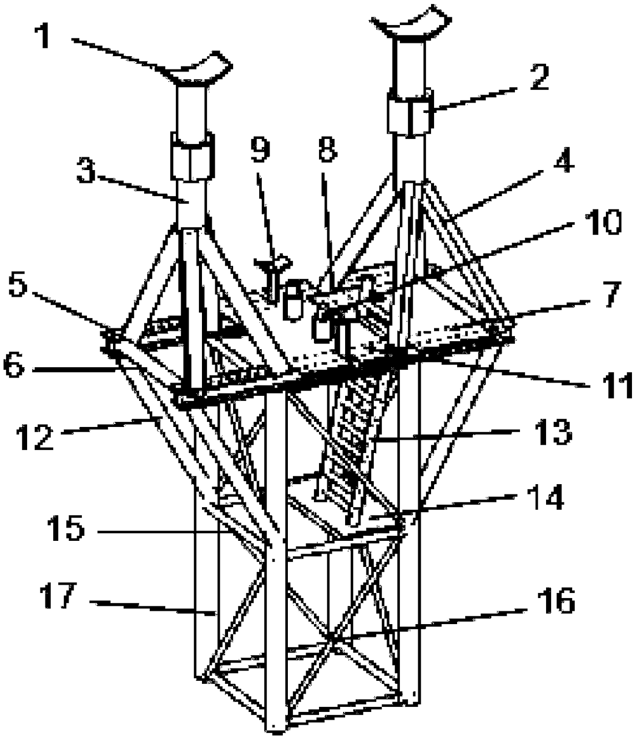
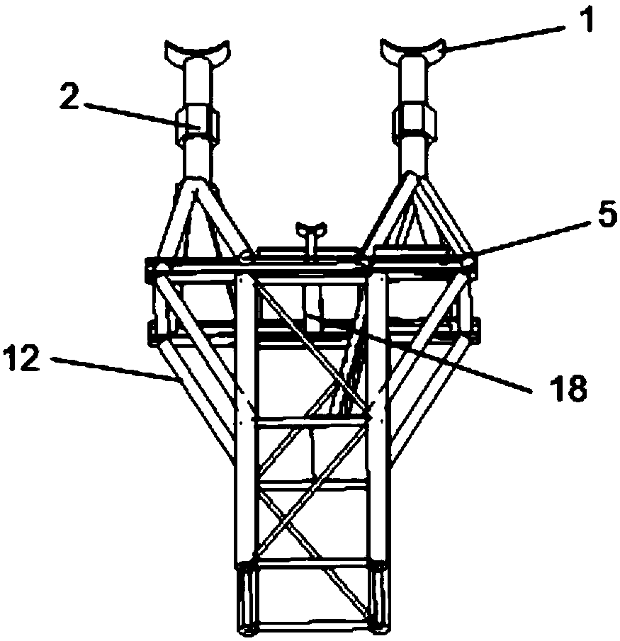
[0046] see figure 1 and figure 2 , this embodiment discloses a new type of precisely adjustable large-span steel pipe truss unloading bracket, including an upper structure, a middle platform structure and a lower structure.
[0047] see Figure 5 , the middle platform structure includes two H-shaped steel platform beams 5 arranged in parallel, and a working platform 11 and a conversion platform 7 welded and fixed on the top surface of the H-shaped steel platform beams 5 . Several steel pipe beams 6 are arranged between the two H-shaped steel platform beams 5 arranged in parallel. The working platform 11 is a plate-like structure as a whole. A concave bayonet groove is provided on the upper surface of the working platform 11 . The lower surface of the working platform 11 is welded with H-shaped steel 18 at the position corresponding to the concave bayonet groove. The working platform 11 is arranged in the middle of the H-shaped steel platform beam 5 . The conversion plat...
Embodiment 2
[0052] This embodiment discloses a method for manufacturing the new type of large-span steel pipe truss unloading bracket described in Embodiment 1, including the following steps:
[0053] 1) Select the standard section at the top of the support frame and establish a center point in the middle, and set up the transition platform 14 and the welding ladder 13.
[0054] 2) Weld the H-shaped steel platform beam 5 on the upper surface of the tower crane standard section.
[0055] 3) Through plane positioning and center measurement, the conversion platform 7, the working platform 11 and the lap plate 8 are sequentially erected on the upper surface of the H-shaped steel platform beam 5.
[0056] 4) Weld the short support column 9 in the concave bayonet groove of the working platform 11, and lay the jack 10.
[0057] 5) Weld support column diagonal brace 4 and bolt support column 3.
Embodiment 3
[0059] This embodiment discloses a precise adjustment function of the new type of precisely adjustable large-span steel pipe truss unloading bracket described in Embodiment 1, to meet the needs of displacement monitoring during unloading of some engineering truss structures, including the following steps:
[0060] 1) The fine-tuning jack 10 slowly lifts the steel truss placed on the bracket, so that the steel truss just breaks away from the tile support 1.
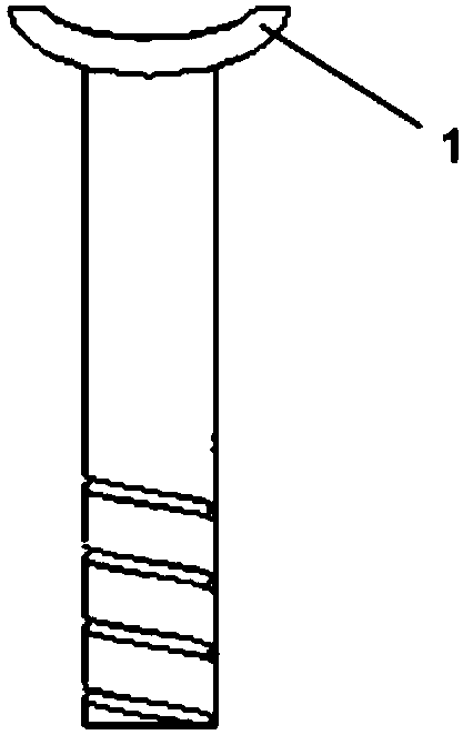
[0061] 2) Turn the adjusting bolt ring 2 clockwise for one turn, and at this time, the bolt supporting column 3 drops by 1mm. Wherein, the internal thread density of the adjusting bolt ring 2 satisfies that the bolt supporting column 3 rises or falls by 1mm every turn. When unloading, screw the adjusting bolt ring 2 to check the deflection and deformation of the truss by the number of turns.
[0062] 3) Use a level to measure the vertical displacement between the truss and the supporting tile 1 and the elevation of the su...
PUM
 Abstract
Description
Claims
Application Information
 - R&D
- Intellectual Property
- Life Sciences
- Materials
- Tech Scout
- Unparalleled Data Quality
- Higher Quality Content
- 60% Fewer Hallucinations
Browse by: Latest US Patents, China's latest patents, Technical Efficacy Thesaurus, Application Domain, Technology Topic, Popular Technical Reports.
© 2025 PatSnap. All rights reserved.Legal|Privacy policy|Modern Slavery Act Transparency Statement|Sitemap|About US| Contact US: help@patsnap.com


