
Permanent magnet fault tolerant motor driving system

A motor drive system, permanent magnet fault-tolerant technology, applied in the control system, motor control, AC motor control, etc., can solve the problems of cogging torque pulsation, loud noise, burning motor windings, etc., and achieve cogging torque pulsation Small size, high system utilization, and the effect of suppressing short-circuit current

Pending Publication Date: 2019-03-22
NANJING UNIV OF SCI & TECH
View PDF3 Cites 7 Cited by
  • Summary
  • Abstract
  • Description
  • Claims
  • Application Information

AI Technical Summary

Problems solved by technology

In the existing major fault-tolerant electric drive systems, for the traditional double-redundancy motors, distributed windings are generally used, which causes the motor windings to be burned out once the windings are short-circuited, and will be damaged due to magnetic field coupling. The output pulsating electromagnetic torque makes the system unable to work normally; although the switched reluctance motor has good fault tolerance, compared with the permanent magnet motor, it has disadvantages such as low power density, large noise and large torque ripple. , so that its application is limited accordingly
In addition, the existing electric drive system still has problems such as cogging torque ripple and short-circuit current are difficult to effectively suppress, the number of power supplies required is too large, and fault tolerance is insufficient.

Method used


Image

  • Permanent magnet fault tolerant motor driving system

Examples


Embodiment

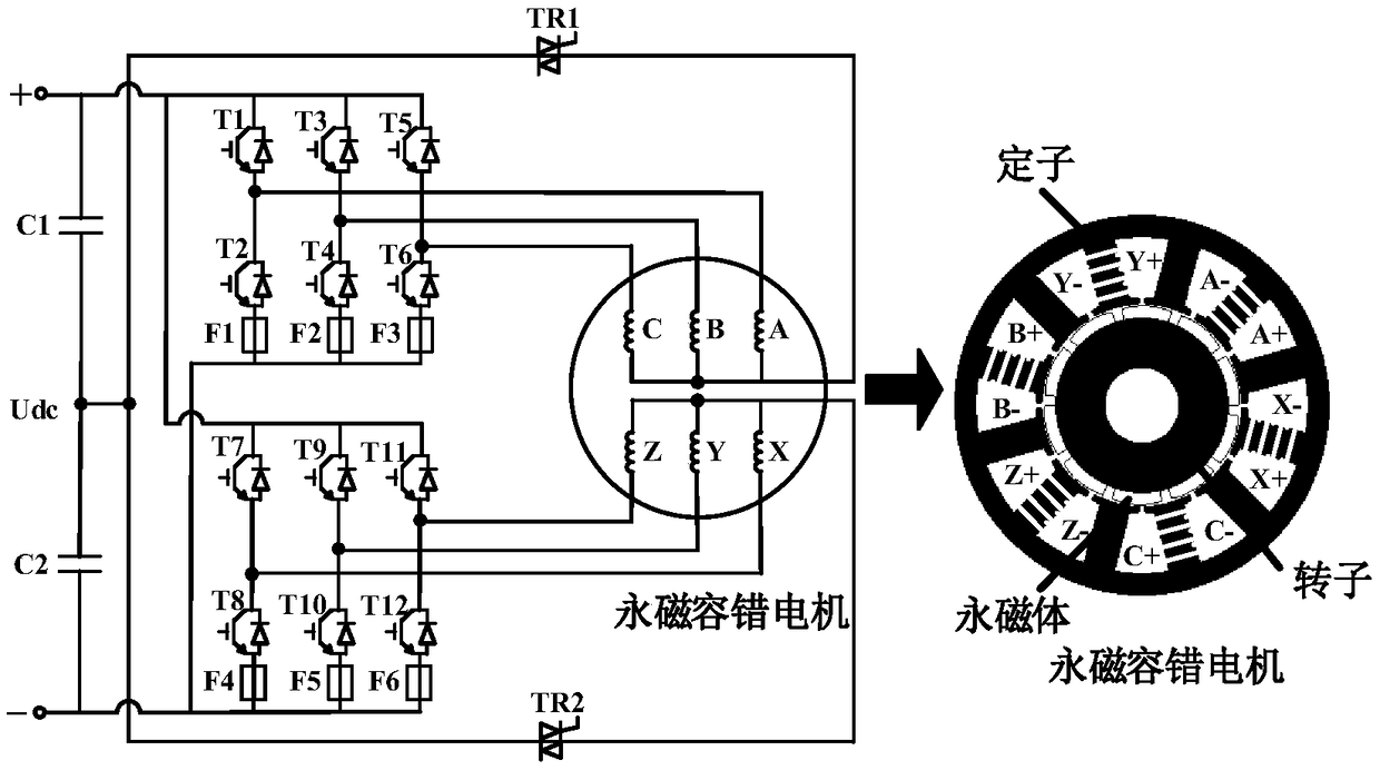
[0031] Such as figure 1 As shown, the present invention is based on a high-reliability electric drive system of a permanent magnet fault-tolerant motor, including a high-reliability permanent magnet fault-tolerant motor, two sets of three-phase full-bridge drive circuits, two bidirectional thyristors, six fuses and an independent 270V DC power supply.

[0032] Further, the permanent magnet fault-tolerant motor is composed of a twelve-slot stator and a five-pole surface-mounted permanent magnet rotor. The twelve-slot stator includes two sets of mutually independent and symmetrical three-phase single-layer centralized tooth-separated windings. The armature windings are ABC windings and XYZ windings; the rotor adopts the rotor magnetic steel centrifugal structure.

[0033] Further, the two sets of three-phase full-bridge drive circuits are respectively composed of six power switch tubes, wherein the three-phase full-bridge circuit composed of six power switch tubes T1, T2, T3, T...


PUM


Abstract

The invention discloses a permanent magnet fault tolerant motor driving system. The system includes a permanent magnet fault tolerant motor, two sets of three-phase full-bridge driving circuits, two bidirectional thyristors, six fuses, and a separate 270V DC power source; the permanent magnet fault-tolerant motor comprises one set of armature ABC windings and one set of XYZ windings which are independent of each other, are symmetrical with respect to each other and are wound in a manner that each slot is wound with one phase of coils in a three-phase single-layer centralized mode; each set ofthree-phase full-bridge driving circuit is composed of six power switching tubes; the two sets of three-phase full-bridge driving circuits respectively control the ABC windings and XYZ windings of the permanent magnet fault-tolerant motor; when the system fails, a corresponding bidirectional thyristor is turned on, so that a half-bridge power conversion circuit with a neutral point is formed, andtherefore, the control of the fault-tolerant operation of the system is realized. The permanent magnet fault tolerant motor driving system of the invention has the advantages of magnetic isolation, physical isolation, thermal isolation, small cogging torque ripple, suppression of short-circuit current, and high fault tolerance, and can realize fault-tolerant operation under a condition that different electrical faults occur alone or simultaneously.

Description

technical field [0001] The invention relates to the technical field of electric drive systems, in particular to a permanent magnet fault-tolerant motor drive system. Background technique [0002] With the development of power electronics technology, motor control technology and rare earth permanent magnet materials, permanent magnet motors are facing new development opportunities and challenges. In addition to requiring high power density and high efficiency, they also need to have high output performance and high reliability. Sex, which has become the key to the development of permanent magnet motors. However, when the motor fails, due to the asymmetrical operation of the motor, the output torque will pulsate, resulting in large mechanical noise, resulting in a decline in the overall performance of the system, especially the greatly reduced output power, or even failure to work normally, seriously endangering the system security. Therefore, for the current electric drive ...

Claims


Application Information

Patent Timeline
IPC IPC(8): H02P25/18H02P25/22H02P29/024H02P29/028
CPCH02P25/18H02P25/22H02P29/025H02P29/027H02P29/028
Inventor 蒋雪峰汤然李运之陈明昊陈鹏飞
Owner NANJING UNIV OF SCI & TECH
Learn More