Few-groove multi-pole permanent magnet fault-tolerant rim propulsion motor

A technology of permanent magnet fault tolerance and rim propulsion, applied in the direction of magnetic circuits, electromechanical devices, electrical components, etc., can solve the problems of increasing production cycle, etc., and achieve the effect of improving operating performance, large slot width, and large winding utilization

Active Publication Date: 2020-05-22
DALIAN MARITIME UNIVERSITY
View PDF6 Cites 10 Cited by
  • Summary
  • Abstract
  • Description
  • Claims
  • Application Information

AI Technical Summary

Problems solved by technology

However, the permanent magnet fault-tolerant rim propulsion motor still adopts a deep and narrow notch structure, and the notch is too small, so it has to be manually off-line, which increases the production cycle

Method used


Image

  • Few-groove multi-pole permanent magnet fault-tolerant rim propulsion motor
  • Few-groove multi-pole permanent magnet fault-tolerant rim propulsion motor
  • Few-groove multi-pole permanent magnet fault-tolerant rim propulsion motor

Examples


Embodiment

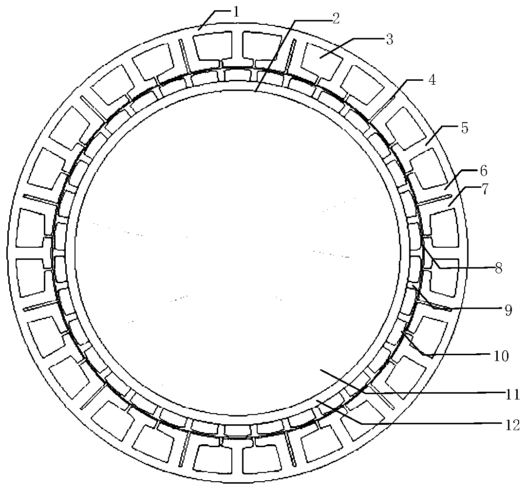
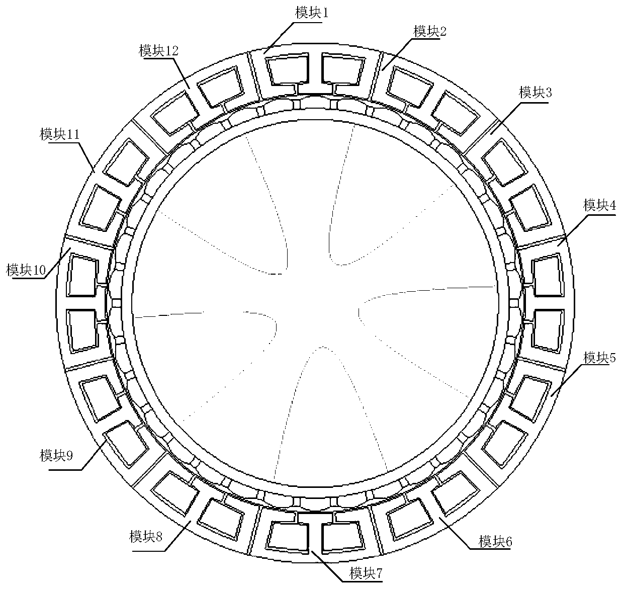
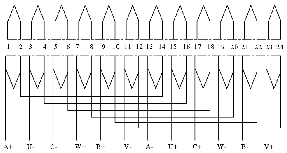
[0022] figure 1 For Example 1, figure 2 For embodiment 2; figure 2 The stator is divided to form a modular structure for easy maintenance. Such as figure 1 As shown, the less-slot multi-pole permanent magnet fault-tolerant rim propulsion motor consists of a stator and a rotor. The stator includes: winding slots 3, isolation slots 4, isolation teeth 1, isolation teeth 2, and armature teeth 5. The windings of the few-slot multi-pole permanent magnet fault-tolerant rim propulsion motor are embedded in the winding slots, which is a single-layer centralized winding structure. The windings only surround the armature teeth, and the winding distribution is as follows: image 3 shown.

Embodiment approach 2

[0023] Wherein the spacer tooth 1, the spacer tooth 2, and the armature tooth 5 have the same width of the teeth, and the same width of the pole shoe. The width of the isolation groove is adjustable, and the preferred width is to reduce the cogging torque ripple. The isolation tank is filled with non-magnetic, anti-corrosion and heat-insulating materials. Increased magnetic isolation and thermal isolation between phases. Embodiment 2 The isolation slot divides the stator to form a modular structure.

[0024] Further, the rotor includes: a rotor yoke 12 , a permanent magnet 10 , an anti-corrosion protection layer 9 and a protection sleeve 8 . The rotor yoke 12 is an integral steel structure without punching, and the propeller 11 is directly welded on the inner diameter of the rotor. The permanent magnet 10 is a surface-mounted permanent magnet or a Halbach array structure with centrifugal height. The permanent magnet 10 is filled with anti-corrosion material, and the anti-co...

Embodiment 1

[0026] The structural parameters of Embodiment 1 are shown in Table 1, and the comparison structure of the 36-slot 30-pole permanent magnet fault-tolerant motor is as follows Figure 4 As shown, the structural parameters are shown in Table 2:

[0027] Table 1 Embodiment 1 Structural parameters

[0028]

[0029]

[0030] Table 2 Structural parameters of 36 slots and 30 poles comparison structure

[0031]

[0032] Embodiment 1 has a larger winding coefficient of 0.996, and the winding coefficient of the comparative structure is 0.966. Embodiment 1 No-load counter electromotive force such as Figure 5 As shown, the no-load back electromotive force of the comparison structure is as Image 6 shown. It can be seen that the no-load back electromotive force of embodiment 1 is not much different from that of the comparison structure, and the utilization rate of the winding is basically unchanged.

[0033] Embodiment 1 can effectively reduce cogging torque ripple, and embo...


PUM


Abstract

The invention discloses a few-groove multi-pole permanent magnet fault-tolerant rim propulsion motor. According to the specific scheme, the motor comprises a stator and a rotor, the stator is providedwith a plurality of winding grooves, armature teeth, first isolation teeth and second isolation teeth, isolation grooves are formed between the first isolation teeth and the second isolation teeth, and the armature teeth, the first isolation teeth and the second isolation teeth are equal in tooth part width and pole shoe width, wherein the number of the winding slots is 4km, the number of magnetic poles of the rotor is k(6m+ / -2), k is a positive integer, and m is the number of phases of the motor. The motor can continuously and stably operate after an open-circuit fault or a short-circuit fault. The motor has the advantages of high winding utilization rate, small cogging torque pulsation and strong magnetic isolation capability and thermal isolation capability. The short-circuit current suppression capability is higher, under the same requirement, the notch width is larger, automatic offline can be achieved, the manufacturing cost is reduced, and batch production becomes possible.

Description

technical field [0001] The invention relates to the technical field of propulsion motors, in particular to a less-slot multi-pole permanent magnet fault-tolerant wheel rim propulsion motor. Background technique [0002] The prior art discloses a permanent magnet fault-tolerant rim propulsion motor for an integrated motor propeller, which belongs to a motor for an underwater propeller. These include stator core, stator slots, armature teeth, spacer teeth, armature windings, large air gap, magnetic pole protection sleeve, magnetic pole protection layer, centrifugal permanent magnet, rotor core, propeller welded inside the rotor core. The number of stator slots is 2km, where k is a positive integer, m is the number of motor phases, there are unequal distances between armature teeth and isolated teeth on the stator, and the number of rotor poles is 2k (m±1). The characteristic of the motor is that it can continue to operate stably after an open circuit fault or short circuit fa...

Claims


Application Information

Patent Timeline
IPC IPC(8): H02K1/16H02K1/27H02K1/28
CPCH02K1/165H02K1/278H02K1/28H02K2213/12
Inventor 朱景伟马瑞林乾宏
Owner DALIAN MARITIME UNIVERSITY
Why Eureka
Try Eureka