A mold grinding device

A mold and grinding disc technology, applied in the field of mold manufacturing, can solve the problems of work efficiency impact, time-consuming and laborious, powder human health damage, etc., and achieve the effect of improving work efficiency

Active Publication Date: 2020-11-17
佛山市南海镕信金属制品有限公司
View PDF6 Cites 0 Cited by
  • Summary
  • Abstract
  • Description
  • Claims
  • Application Information

AI Technical Summary

Problems solved by technology

[0002] In the traditional mold making process, the mold often has burrs and other situations, which affect the precision of the mold. In the current mold manufacturing process, the mold is usually mass-produced and then polished. Most of them are manually polished. The current use method is time-consuming and laborious. Work efficiency is affected, and the powder produced by artificial grinding will also cause great damage to human health

Method used


Image

  • A mold grinding device
  • A mold grinding device
  • A mold grinding device

Examples


Embodiment 1

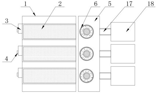
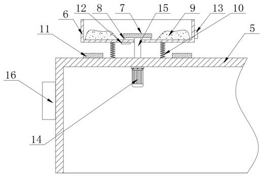
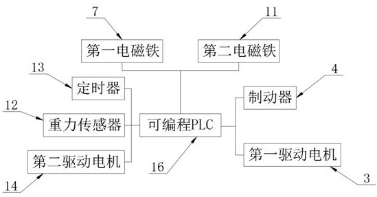
[0025] The present invention provides such Figure 1-3 A mold grinding device shown includes a feeder 1, a conveyor belt 2 is provided on the top of the feeder 1, a first drive motor 3 is provided at one end of the conveyor belt 2, and a brake is provided on one side of the first drive motor 3 4. There is a grinding frame 5 on one side of the feeder 1, and a grinding disc 6 is installed on the top of the grinding frame 5. The grinding disc 6 is made of iron material. The gravity sensor 12 senses the weight increase and transmits the signal to Programmable PLC16, programmable PLC16 controls the brake 4 to stop the continuous feeding of the conveyor belt 2, the inside of the grinding disc 6 is provided with a first electromagnet 7, and a deformation pad is provided between the first electromagnet 7 and the inner wall of the grinding disc 6 8. The outside of the first electromagnet 7 is provided with grinding sand 9, a first return spring 10 is provided between the grinding disc ...

Embodiment 2

[0029] The present invention provides such Figure 4-6 As shown in a mold grinding device, one end of the discharge slideway 17 is provided with a storage box 18, and the connection between the storage box 18 and the discharge slideway 17 is provided with a through groove 19, and the inner wall of the storage box 18 is provided with Buffer pad 20, the cavity of the storage box 18 is provided with a support plate 21, a second return spring 22 is provided between the support plate 21 and the inner wall of the storage box 18, and the mold falls to the top of the support plate 21 and is driven by its own weight. The two return springs 22 shrink, thereby realizing the storage mode of the layered arrangement of the moulds, the discharge slide 17 is arranged obliquely, the through groove 19 runs through the storage box 18, and the through groove 19 is matched with the discharge slide 17 , the user takes out the polished mold from the grinding disc 6 and puts it on the discharge slide...


PUM


Abstract

The invention discloses a mold grinding device which comprises a feeder. A grinding rack is arranged on one side of the feeder. Grinding discs are arranged at the top of the grinding rack. A first electromagnet is arranged in each grinding disc. A deformation mat is arranged between each first electromagnet and the inner wall of the correspondingly grinding disc. Grinding sand is arranged on the outer portion of each first electromagnet. First reset springs are arranged between each grinding disc and the grinding rack. Second electromagnets are arranged at the top of the grinding rack. A gravity sensor is arranged at the bottom of each grinding disc. A timer is arranged on the outer wall of each grinding disc. A second drive motor is arranged in an inner cavity of the grinding rack. A PLCis arranged on one side of the grinding rack. According to the mold grinding device, through the arrangement of the grinding rack and the grinding discs, after the PLC controls the first electromagnetto be powered on to attract a mold and controls the second electromagnet to drive the positions of the grinding discs to be lifted under the action of resilience force of the first reset springs after the second electromagnets are powered off, the second drive motors work to drive molds to rotate through transmission rods and the first electromagnets, and grinding is carried out.

Description

technical field [0001] The invention relates to the technical field of mold manufacturing, in particular to a mold grinding device. Background technique [0002] In the traditional mold making process, the mold often has burrs and other situations, which affect the precision of the mold. In the current mold manufacturing process, the mold is usually mass-produced and then polished. Most of them are manually polished. The current use method is time-consuming and laborious. Work efficiency is affected, and the powder produced by artificial grinding will also cause great damage to human health. [0003] Therefore, it is necessary to invent a mold polishing device to solve the above problems. Contents of the invention [0004] The object of the present invention is to provide a mold grinding device, the forming mold is conveyed to the inside of the grinding disc through the conveyor belt, the gravity sensor senses the weight increase and transmits the signal to the programmab...

Claims


Application Information

Patent Timeline
Patent Type & Authority Patents(China)
IPC IPC(8): B24B31/02B24B31/12B24B41/06B24B49/00B24B51/00B24B41/00
CPCB24B31/02B24B31/12B24B41/005B24B41/06B24B49/00B24B51/00
Inventor 林荣斌
Owner 佛山市南海镕信金属制品有限公司
Why Eureka
Try Eureka