Fringe locking type holographic interference photoetching system and fringe locking method

A holographic interference and lithography system technology, applied in microlithography exposure equipment, optics, optomechanical equipment and other directions, can solve problems such as the decrease of the contrast of recording fringes

Active Publication Date: 2019-03-26
SUZHOU UNIV
View PDF5 Cites 2 Cited by
  • Summary
  • Abstract
  • Description
  • Claims
  • Application Information

AI Technical Summary

Problems solved by technology

[0003] In order to solve the technical problem of the random drift of the interference fringes during long-time moving exposure, which leads to the decrease of the contrast of the recording fringes, the present invention proposes a fringe-locked holographic interference lithography system, including a laser, a beam sampling grating, a half-wave plate, a beam splitting prism, the first A plane mirror, a second plane mirror, a third plane mirror, a first acousto-optic modulator, a first ultrasonic generator, a second acousto-optic modulator, a second ultrasonic generator, a first spatial filter, a second Two spatial filters, the first collimator lens, the second collimator lens, the grating substrate to be exposed, the reference grating, the first high-speed photodetector, the second high-speed photodetector, PID controller, single-chip microcomputer; the reference The grating is set on the grating substrate to be exposed, and the surface of the reference grating is in the same plane as the surface of the grating substrate to be exposed; the light emitted by the laser passes through the beam sampling grating, and its 0th-order transmitted and diffracted light enters the beam splitting prism to be divided into transmitted beam and reflected beam. The light beam, where the transmitted light beam passes through the half-wave plate, then passes through the first plane mirror and the second plane mirror, enters the first acousto-optic modulator, and the -1 order diffracted light of the first acousto-optic modulator enters the first spatial filter , then pass through the first collimator lens, expand the beam into parallel light, and finally project it onto the grating substrate to be exposed and the reference grating; the reflected beam passes through the third plane mirror, enters the second acousto-optic modulator, and the second acousto-optic modulator The -1st-order diffracted light of the filter enters the second spatial filter, then passes through the second collimator lens, expands the beam into parallel light, and finally projects on the grating substrate to be exposed and the reference grating; the transmitted beam and the reflected beam are on the exposed Interference on the surface of the ...

Method used


Image

  • Fringe locking type holographic interference photoetching system and fringe locking method
  • Fringe locking type holographic interference photoetching system and fringe locking method
  • Fringe locking type holographic interference photoetching system and fringe locking method

Examples


Embodiment 1

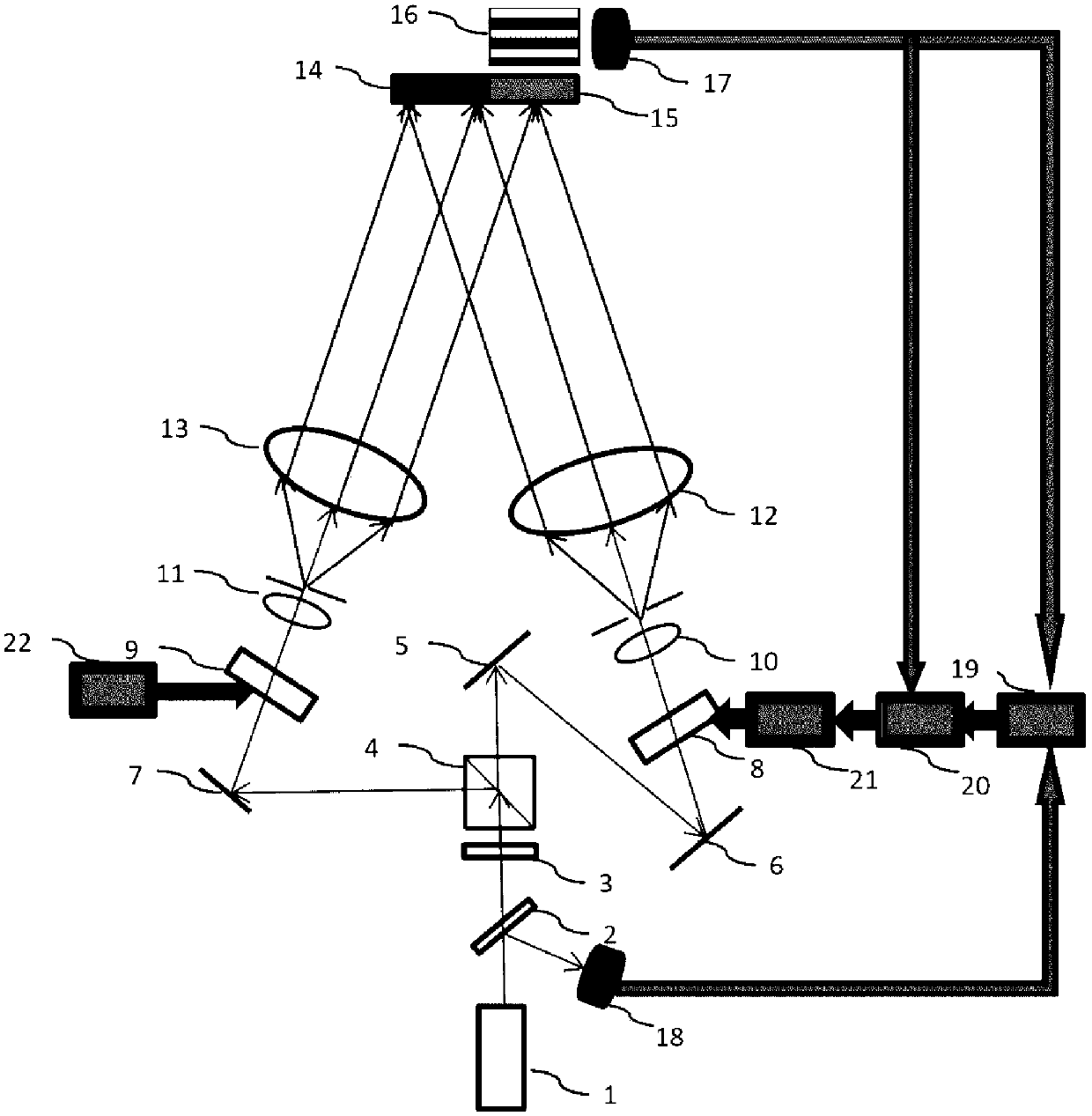
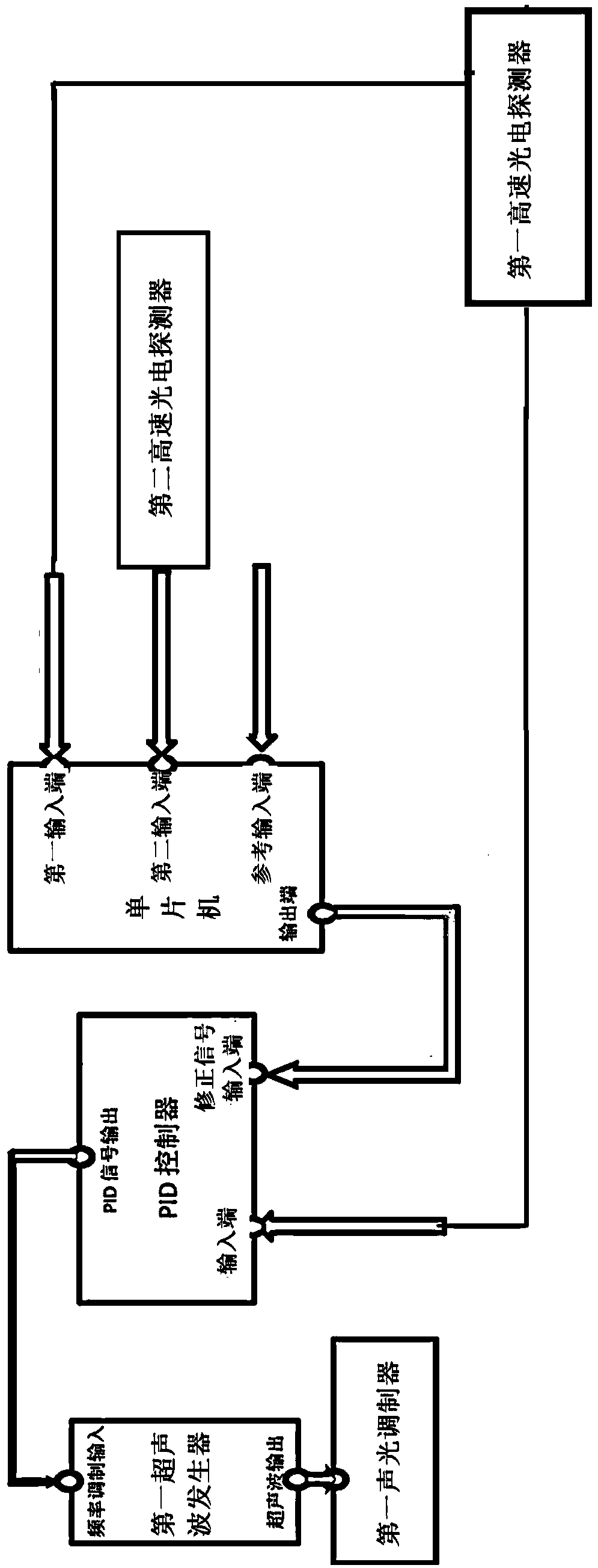
[0017] A fringe-locked holographic interference lithography system, such as figure 1 As shown, it includes a laser 1, a beam sampling grating 2, a half-wave plate 3, a beam splitting prism 4, a first plane mirror 5, a second plane mirror 6, a third plane mirror 7, and a first acousto-optic modulator 8 , the first ultrasonic generator 21, the second acousto-optic modulator 9, the second ultrasonic generator 22, the first spatial filter 10, the second spatial filter 11, the first collimating lens 12, the second collimating lens 13 , the grating substrate 14 to be exposed, the reference grating 15, the first high-speed photodetector 17, the second high-speed photodetector 18, the PID controller 20, the single-chip microcomputer 19; the reference grating is arranged on the grating substrate to be exposed, And the surface of the reference grating is in the same plane as the surface of the grating substrate to be exposed; the light emitted by the laser passes through the beam sampli...

Embodiment 2

[0019] A fringe locking method for a fringe-locked holographic interference lithography system, comprising the following steps,

[0020] Step 1, making reference grating: After adjusting the optical path of the holographic interference lithography system, place the reference grating substrate to be prepared at the position of the reference grating, set the frequency of the first ultrasonic generator to f1 (105MHz~115MHz), set the second The frequency of the ultrasonic generator is f2 (105MHz~115MHz), and f1=f2 is guaranteed. The reference grating substrate to be prepared is exposed and developed, and the developed reference grating is placed in its original position to call out Moiré fringes. The fringe period interval is 1cm~2cm, project the moiré fringes into the first high-speed photodetector, and adjust the position of the first high-speed photodetector so that its photosensitive surface is located in the middle of the dark moiré fringe and the bright fringe.

[0021] Step...


PUM


Abstract

The invention belongs to the technical field of information optics, and relates to a holographic interference photoetching system. In order to solve the problem that the interference fringe drift holographic grating contrast ratio decreases, a first high-speed photoelectric detector is utilized to acquire a moire fringe light intensity signal on the surface of a reference grating, and transmit thelight intensity signal to a single chip computer and a PID controller at the same time; a second high-speed photoelectric detector monitors a light intensity signal of a laser through a light beam sampling grating, the light intensity signal is transmitted to the single chip computer, and a signal output end of the PID controller transmits to a frequency modulation input end of a first ultrasonicgenerator; and when the PID controller judges that the light intensity signal detected in real time by the first high-speed photoelectric detector changes, the PID controller outputs a feedback signal to the first ultrasonic generator, the frequency of the first ultrasonic generator changes correspondingly, the phase of the -1 level diffraction light of a first acoustic optical modulator changes,accordingly the phase of the moire fringe is locked, and locking of the interference fringe phase is achieved.

Description

technical field [0001] The invention belongs to the technical field of information optics and relates to a holographic interference photolithography system. Background technique [0002] When shooting a large-scale holographic grating, a long exposure time is required due to the weak shooting light intensity. However, external vibration, air flow, temperature fluctuation and other factors will change the relative phase of the object light and reference light, and the interference fringes formed by them will drift randomly, thus reducing the contrast of the recording fringes. None of the current holographic lithography systems can solve the problem of interference fringe drift over a long period of time. Therefore, for long-term exposure, active vibration isolation methods are required to control the drift of interference fringes. The current existing fringe locking method: the invention patent with the patent number of 2006100399676 discloses the linear array CCD fitting fr...

Claims


Application Information

Patent Timeline
IPC IPC(8): G03F7/20
CPCG03F7/70408
Inventor 邹文龙蔡志坚李朝明陈新荣吴建宏刘全
Owner SUZHOU UNIV
Why Eureka
Try Eureka