Supercharge Your Innovation With Domain-Expert AI Agents!

Visual positioning welding assembly method

A visual positioning and welding technology, applied in auxiliary devices, welding equipment, welding equipment, etc., can solve the problems of positioning reference wear and positioning, takt loss, high energy consumption, and achieve the goal of reducing import costs, reducing investment, and improving utilization. Effect

Inactive Publication Date: 2019-03-29
施努卡(苏州)智能装备有限公司
View PDF14 Cites 3 Cited by
  • Summary
  • Abstract
  • Description
  • Claims
  • Application Information

AI Technical Summary

Problems solved by technology

[0003] At present, the automatic production line of automobile welding workshop mainly uses fixtures for body positioning, which has limitations in flexibility, certain beat loss, inaccurate positioning due to wear of positioning reference, and high energy consumption.

Method used


Image

  • Visual positioning welding assembly method
  • Visual positioning welding assembly method
  • Visual positioning welding assembly method

Examples


Embodiment 1

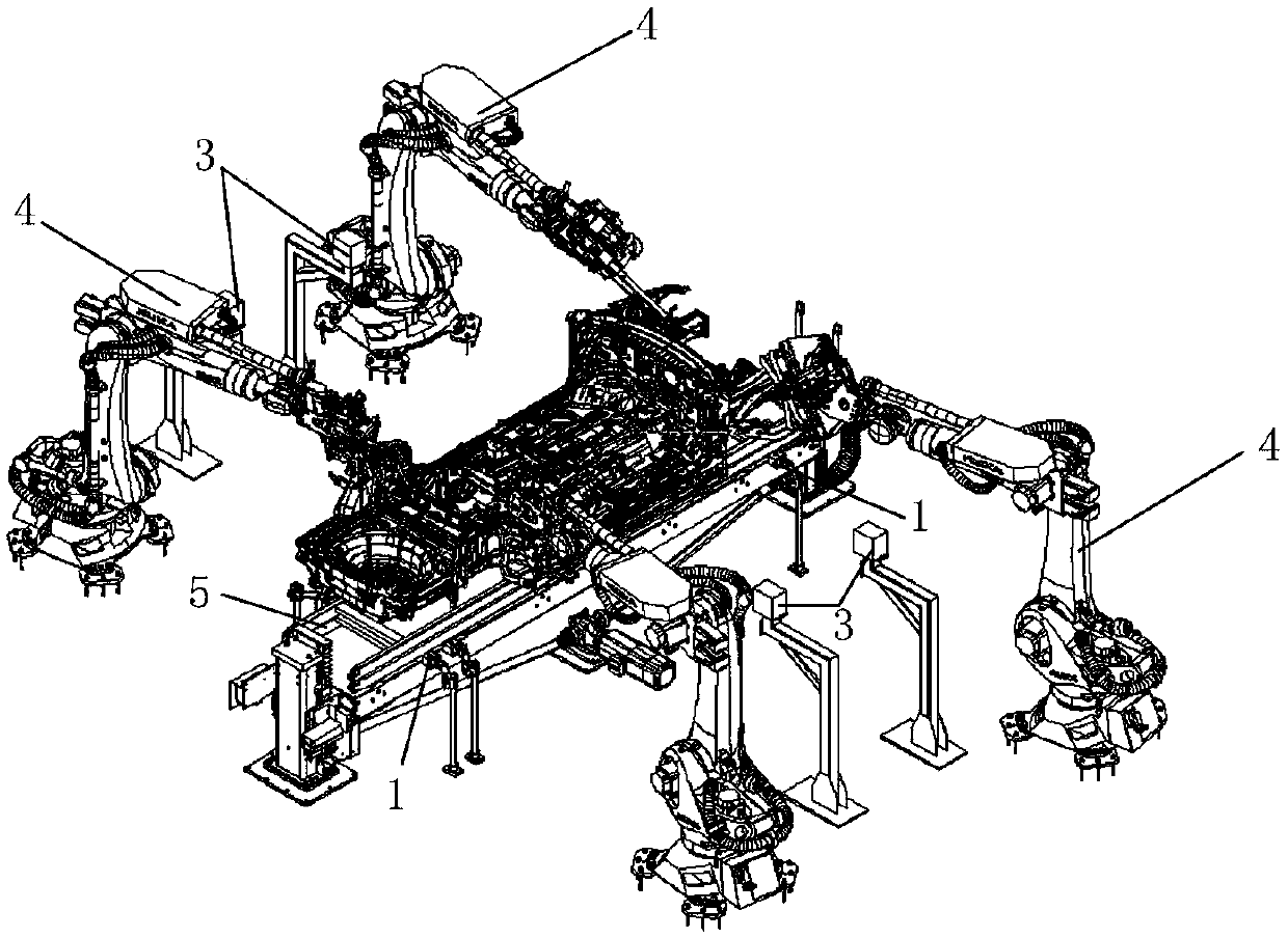
[0029] The visual positioning and welding system provided by the embodiment of the first aspect of the present invention optimizes the positioning mode of the welding production line, uses machine vision technology to position the vehicle body, and guides the welding robot 4 to perform subsequent processes, so that the same welding The assembly line is equipped with fast and flexible switching of any model, which avoids the development and processing of many non-standard fixtures and fixtures, and uses non-contact positioning to avoid deviations in body size caused by repeated positioning, reducing the introduction cost of model upgrades, and reducing the introduction of subsequent projects At the same time, improve the utilization rate of the beat and create more value for the enterprise.

[0030] In the optional solution of this embodiment, further, the visual information of the positioning point includes the deviation value of the position of the vehicle body and the deforma...

Embodiment 2

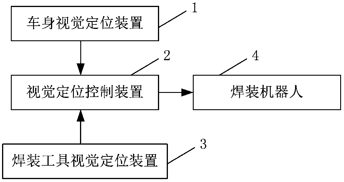
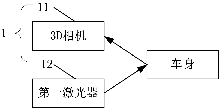
[0040] The embodiment of the second aspect of the present invention provides a visual positioning welding method, including: the first visual sensor 11 collects the visual information of the positioning point of the vehicle body, wherein the visual information of the positioning point includes the deviation value of the position of the vehicle body and the deformation information of the positioning point The second visual sensor 21 collects the tool vision information of the welding robot 4, wherein the tool vision information includes the welding robot 4 position information and the welding tool position information on the welding robot 4; the visual positioning control device 2 receives the positioning point vision information and tool vision information, and control the welding robot 4 to adjust the position and processing path of the welding tool according to the visual information of the positioning point and the tool vision information, so as to guide the welding robot 4 t...


PUM


Abstract

The invention relates to the technical field of automobile fabrication, in particular to a visual positioning welding assembly method. The positioning welding method comprises the specific steps thata, a vehicle body visual positioning device is utilized to collect positioning point visual information of a vehicle body; b, welding assembly tool visual positioning devices are utilized to collect tool visual information of welding assembly robots; and c, a visual positioning control device is utilized to receive the positioning point visual information and the tool visual information to generate control commands, and the welding assembly robots are controlled to adjust positions and machining paths of welding assembly tools to guide the welding assembly robots to finish the welding assemblywork. According to the visual positioning welding assembly method, optimizing is performed on the positioning method of a welding assembly production line, positioning is performed on the vehicle body adopting a machine vision technology, the welding assembly robots are guided to perform the subsequent process, one same welding assembly production line is made to have any type of rapid flexible switching, development and machining of many non-standard tooling fixtures are avoided, the introduction cost of vehicle type upgrading is reduced, the investment in subsequent projects is reduced, andthe takt time use ratio is increased.

Description

technical field [0001] The invention relates to the technical field of automobile manufacturing, in particular to a visual positioning welding method. Background technique [0002] The welding production line is the key to automobile manufacturing, and various fixtures in the welding production line are the top priority of the welding assembly line. Among the four major processes of automobile manufacturing, welding is particularly important. In the preliminary process planning of welding, the design of body welding fixtures and production lines is a very critical link. For the car body, the assembly and welding process of the body line is mainly composed of three parts: pre-assembly, spot welding and repair welding. Among them, the spot welding process is the most critical, and it is basically completed in the fixture. The fixtures in the welding production line determine the quality of the body, the flexibility of the production line and the production cycle, which is ve...

Claims


Application Information

Patent Timeline
IPC IPC(8): B23K37/00B23K31/02
CPCB23K31/02B23K37/00
Inventor 雷金波谭思源汪勇王聪然赵轩张仁钰杨峰
Owner 施努卡(苏州)智能装备有限公司
Features
  • R&D
  • Intellectual Property
  • Life Sciences
  • Materials
  • Tech Scout
  • Unparalleled Data Quality
  • Higher Quality Content
  • 60% Fewer Hallucinations
Learn More