Micro-rail traffic system

A traffic system, micro-rail technology, applied in the traffic field

Active Publication Date: 2019-03-29
CRRC TANGSHAN CO LTD
View PDF11 Cites 10 Cited by
  • Summary
  • Abstract
  • Description
  • Claims
  • Application Information

AI Technical Summary

Problems solved by technology

[0004] In view of this, the present invention expects to provide a kind of micr...

Method used


Image

  • Micro-rail traffic system
  • Micro-rail traffic system
  • Micro-rail traffic system

Examples


Embodiment 1

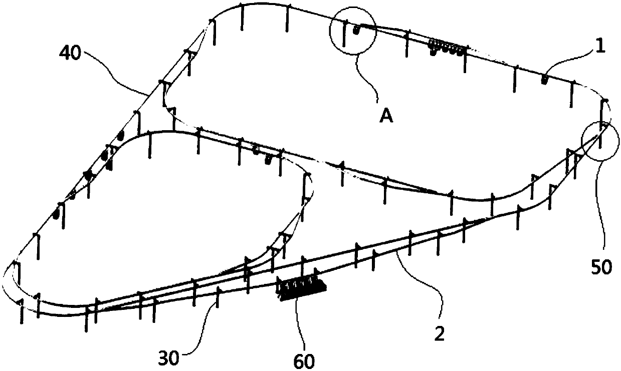
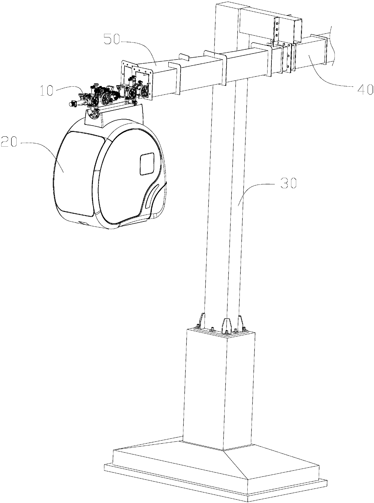
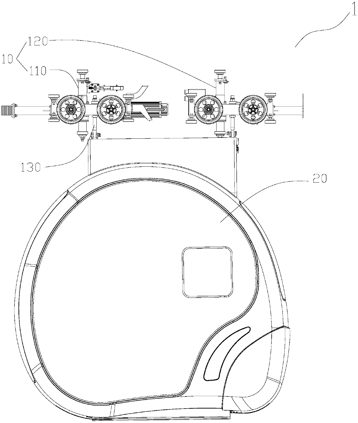
[0273] Such as Figure 3-28 As shown, the micro-rail transit system related to the present invention includes a vehicle system 1, and the vehicle system 1 includes a carriage 20 and a running mechanism 10, and the running mechanism 10 includes a hanging device 130 installed below it, and the top of the carriage 20 is connected to the The hanging device 130 is connected; the traveling mechanism 10 drives the carriage 20 to run along the suspended track structure 40 through the hanging device 130 .

[0274] Specifically, the running mechanism 10 includes a vehicle frame and a wheel pair, the vehicle frame is a frame structure of the running mechanism, and the wheels are mounted on the vehicle frame. The width of vehicle frame is less than the width of suspended track structure 40, and after vehicle frame is installed on the wheel pair, can run along suspended track structure 40. The shape and structure of the frame are not limited here. In practice, a single carriage 20 can be...

Embodiment 2

[0283] In the specific operation of the micro-rail transportation system, a turnout will be set on the suspended track structure 40 to provide a path for the steering of the micro-rail vehicle system. Correspondingly, the running mechanism 10 is provided with a steering mechanism for assisting the running mechanism to turn when passing the switch. 170, such as Figure 6-8 As shown, the steering mechanism 170 includes an upper steering device 171 and a steering drive device. The upper steering device 171 is installed on the upper surface of the vehicle frame. The vehicle frame here can be the above-mentioned first vehicle frame 111 or the second vehicle frame 121. , is not limited in the present invention; the steering drive device is installed in the vehicle frame and is used to drive the upper steering device 171 to run. Preferably, the steering drive is a stepper motor 174, and the stepper motor 174 has two output shafts, and the two output shafts are output synchronously. ...

Embodiment 3

[0294] In the present invention, the suspension device 130 is used as the connection device connecting the carriage 20 and the running mechanism 10, and its structure design is reasonable, its strength is high, and its safety performance is good.

[0295] Specifically, such as Figure 17 As shown, the suspension device 130 includes: a load-bearing rod 131 and a suspension pin 133. The load-bearing rod 131 is vertically arranged, and its top end passes through the vehicle frame upwards and is fixed with the vehicle frame. The mounting base 214 is connected; the vehicle frame here can be the above-mentioned first vehicle frame 111 or the second vehicle frame 121 , and the present invention is not limited in comparison. Preferably, there are two suspension pins 133, which are symmetrically installed on both sides of the load-bearing bar 131, and the two suspension pins 133 are connected together by cotter pins or nuts (not shown in the figure).

[0296] The load-bearing rod 131 ...


PUM

PropertyMeasurementUnit
Total lengthaaaaaaaaaa
Thicknessaaaaaaaaaa

Abstract

The present invention relates to a micro-rail traffic system including a rail system, a train system and a dispatching control system. The rail system includes a suspended track structure for suspending the train system. The train system includes a carriage and a running mechanism. The carriage is suspended in the track structure by the running mechanism that drives the carriage to run along the track structure. The dispatching control system includes a dispatching control center that controls the train system to operate on the track structure. The micro-rail traffic system provided by the invention is simple in overall structure, convenient to install, disassemble and expand, reduces construction and operation costs, improves adaptability to various complex terrains, minimizes occupancy of original roads, and improves the composite use degree of roads, is convenient for passengers to travel.

Description

technical field [0001] The invention relates to the field of transportation, in particular to a micro-rail transportation system. Wherein, the micro-track of the present invention refers to: the track width is the suspended traffic system below 600mm. Background technique [0002] Personal Rapid Transit (PRT, Personal Rapid Transit) is a new type of rail transit system and a transportation solution for the purpose of meeting individual transportation needs. This system can meet the transportation needs of each specific individual for different travel time, origin, destination, route, etc. The use of PRT does not require travel plans to be made according to the vehicle schedule, nor does it need to change vehicles midway, as long as they sit in the vehicle, the vehicle will automatically send passengers to their destinations, which is convenient to use. [0003] At present, several major PRTs in the world all adopt the scheme that the vehicle runs on a special track, and ca...

Claims


Application Information

Patent Timeline
IPC IPC(8): B61B3/02B61B1/00
CPCB61B1/00B61B3/02
Inventor 周军年尹叶红陈亮吴胜权任刚张晓军王广明李明高杲晓锋姜茹佳
Owner CRRC TANGSHAN CO LTD
Why Eureka
Try Eureka