
Spiral wave plasma propelling unit without neutralizer

A plasma and propulsion device technology, applied in the field of plasma propulsion devices, can solve the problems of spacecraft self-charging, communication and electronic device damage, acceleration, etc., and achieve the effects of avoiding self-charge, prolonging life, and high ionization degree

Pending Publication Date: 2019-03-29
HENAN POLYTECHNIC UNIV
View PDF0 Cites 8 Cited by
  • Summary
  • Abstract
  • Description
  • Claims
  • Application Information

AI Technical Summary

Problems solved by technology

[0002] The attitude adjustment of traditional satellite platforms and other types of spacecraft is mainly through chemical propulsion. There are many problems in the application of chemical propulsion. At present, electric propulsion is mainly developed in this field. Compared with chemical propulsion, the main advantage of electric propulsion is high specific impulse. High thrust accuracy, etc.; plasma thrusters are commonly used in electric propulsion. Most of the current plasma thrusters use the method of accelerating positive ions to generate thrust. Otherwise, it will lead to self-charging of the spacecraft, causing damage to its communication and electronic devices, and the performance of the neutralizer of this type of plasma thruster becomes an important factor restricting the working state and life of the electric thruster. Therefore, a A plasma propulsion device without a neutralizer

Method used


Image

  • Spiral wave plasma propelling unit without neutralizer
  • Spiral wave plasma propelling unit without neutralizer
  • Spiral wave plasma propelling unit without neutralizer

Examples


Embodiment Construction

[0014] The technical solutions of the present invention will be clearly and completely described below, and obviously, the described embodiments are part of the embodiments of the present invention, not all of them. Based on the embodiments of the present invention, all other embodiments obtained by persons of ordinary skill in the art without making creative efforts belong to the protection scope of the present invention.

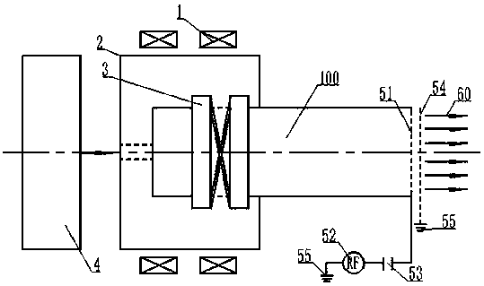
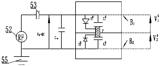
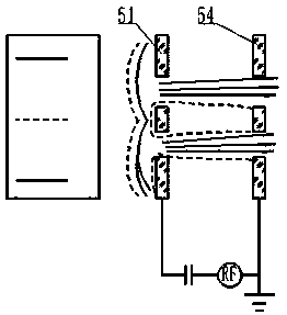
[0015] Such as Figure 1-Figure 4 A helicon wave plasma propulsion device without a neutralizer shown includes a working fluid supply unit 4 and a helicon wave plasma source, the helicon wave plasma source includes a discharge chamber 100, an electromagnetic coil 1, and a ceramic sleeve 2 And the helical wave excitation antenna 3, the helical wave excitation antenna 3 is connected to the radio frequency power source and sleeved on the outside of the front part of the discharge chamber 100, the helical wave excitation antenna 3 and the discharge chamber 100...


PUM


Abstract

The invention discloses a spiral wave plasma propelling unit without a neutralizer. The spiral wave plasma propelling unit comprises a working medium supply unit and a spiral wave plasma source, the spiral wave plasma source comprises a discharging room, electromagnetic coils, a ceramic sleeve and a spiral wave excitation antenna. The spiral wave excitation antenna is connected with a radio frequency power source and sleeves the outer side of the front of the discharging room, the spiral wave excitation antenna and the discharging room where the spiral wave excitation antenna is located are located inside the ceramic sleeve, and the electromagnetic coils sleeve the exterior of the ceramic sleeve; a gas inlet communicated with the working medium supply unit is formed in the front end of thedischarging room, an accelerating grid electrode and a decelerating grid electrode are sequentially arranged at the rear end of the discharging room, and the accelerating grid electrode is connectedwith a radio frequency power source through a capacitor. The spiral wave plasma propelling unit has the advantages that generating and accelerating of plasmas are free of electrode erosion, meanwhile,the advantage of a high ionization degree of the plasmas is considered, and compared with a traditional magnetic spray nozzle propelling unit, specific impulse is higher, thrust is larger, and performance is better.

Description

technical field [0001] The invention relates to a helicon wave plasma propulsion device without a neutralizer, belonging to the technical field of spacecraft propulsion. Background technique [0002] The attitude adjustment of traditional satellite platforms and other types of spacecraft is mainly through chemical propulsion. There are many problems in the application of chemical propulsion. At present, electric propulsion is mainly developed in this field. Compared with chemical propulsion, the main advantage of electric propulsion is high specific impulse. High thrust accuracy, etc.; plasma thrusters are commonly used in electric propulsion. Most of the current plasma thrusters use the method of accelerating positive ions to generate thrust. Otherwise, it will lead to self-charging of the spacecraft, causing damage to its communication and electronic devices, and the performance of the neutralizer of this type of plasma thruster becomes an important factor restricting the ...

Claims


Application Information

Patent Timeline
IPC IPC(8): F03H1/00
CPCF03H1/0018F03H1/0081
Inventor 徐永豪石峰王国东王昊张影朱红伟刘小莲
Owner HENAN POLYTECHNIC UNIV
Learn More