Efficient heat exchange structure of compressed air refrigeration dryer

A technology of compressed air and heat exchange structure, which is applied in the direction of heat exchanger shell, indirect heat exchanger, heat exchanger type, etc. It can solve the problems that moisture is easily taken away by the air flow, the structure cannot be compacted, and the production is complicated. Achieve the effect of reducing the risk of corrosion leakage and solder joint leakage, reducing leakage, and simplifying procurement

Inactive Publication Date: 2019-04-02
FOSHAN TIANDI YUANYI PURIFICATION EQUIP
View PDF0 Cites 3 Cited by
  • Summary
  • Abstract
  • Description
  • Claims
  • Application Information

AI Technical Summary

Problems solved by technology

[0002] The existing heat exchange structures of compressed air dryers mainly fall into the following categories: the first category is the heat exchange structure of refrigerated dryers, such as image 3 As shown, 1a-cooling and heat exchanger, 2a-evaporator, 3a-gas-liquid separator are made of separate barrels, the structure is complicated, the production is complicated, and the volume is huge. The evaporator adopts copper-aluminum fin type or stainless steel fin type. Heater, the gap between the fins is small, the condensed water is easy to freeze in the evaporator, resulting in ice blockage
The second type, plate or plate-fin type cold dryer heat exchanger, such as Figure 4 As shown, this heat exchange structure has the following problems: 1. Aluminum plate-fin heat exchangers or stainless steel plate heat exchangers are used for cold and heat exchange and evaporators, and the welding joints are easy to leak and cannot be repaired; 2. The plates are thin , is also easy to corrode and perforate and cannot be repaired; 3. Due to the small size, the steam-water separation effect is not good; if an external steam-water separator is installed, the compact structure cannot be achieved; 4. The gap between the plates is small, and it is easy to be blocked by dirt. The accumulation of more dirt will

Method used


Image

  • Efficient heat exchange structure of compressed air refrigeration dryer
  • Efficient heat exchange structure of compressed air refrigeration dryer
  • Efficient heat exchange structure of compressed air refrigeration dryer

Examples


Embodiment 1

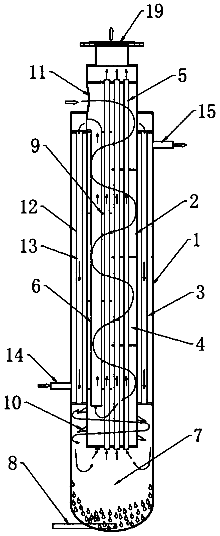
[0029] Embodiment 1: as figure 1 As shown, a high-efficiency heat exchange structure of a compressed air refrigeration dryer includes a vertically arranged first tube 1, and also includes a second tube 2 arranged in the inner cavity of the first tube 1, and the first The tube 1 and the second tube 2 are coaxially arranged, and the structure is symmetrical. The upper and lower ends of the first tube 1 and the second tube 2 are sealed, and the top of the first tube 1 protrudes from the top of the second tube 2. A first cavity 3 is formed between the inner wall of the tube 1 and the outer wall of the second tube 2, the inner cavity of the second tube 2 forms a second cavity 4, and an air inlet 11 is opened on the upper part of the second tube 2 and communicated with the The second cavity 4, the second tube 2 is provided with a plurality of first heat exchange tubes 5 up and down, and the plurality of first heat exchange tubes 5 are evenly distributed in the second cavity 4, and ...

Embodiment 2

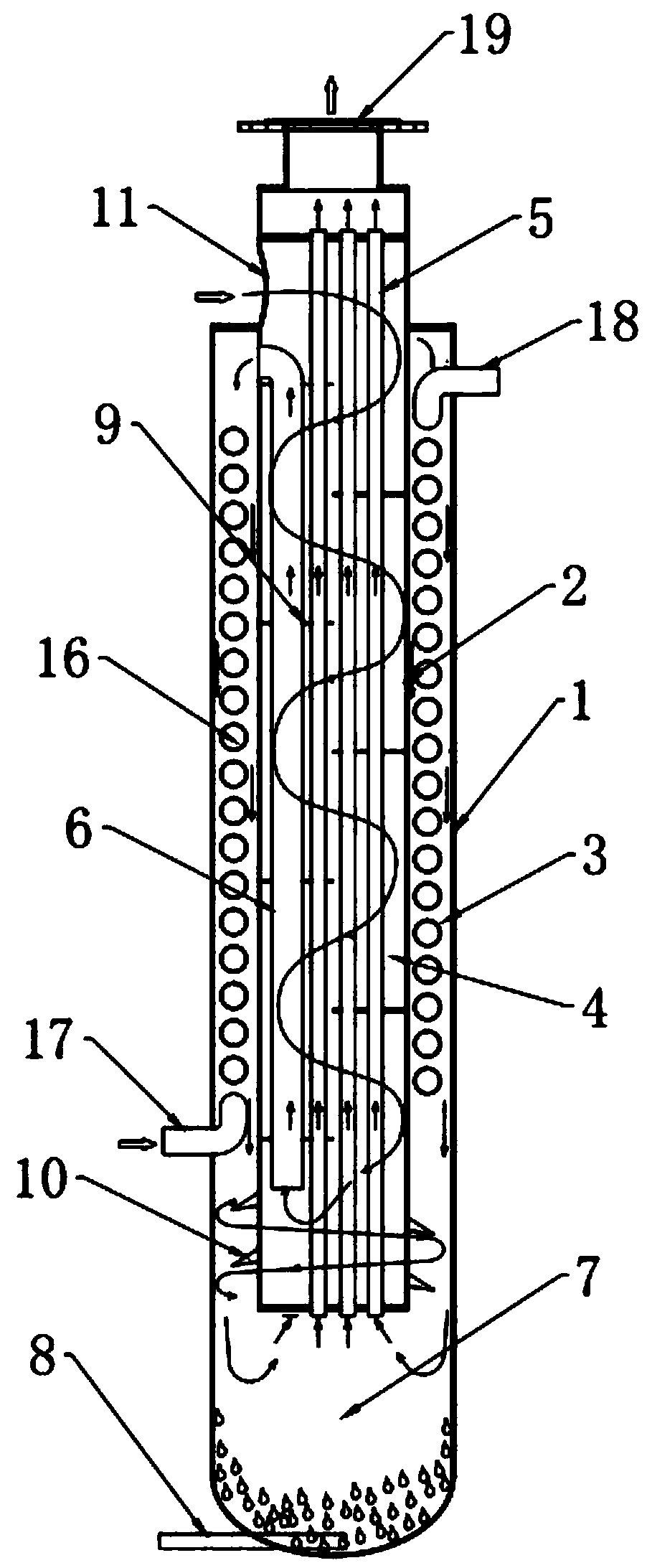
[0032] Embodiment 2: refer to figure 2 , a high-efficiency heat exchange structure for a compressed air refrigeration dryer, comprising a vertically arranged first tube 1, and also including a second tube 2 arranged in the inner cavity of the first tube 1, and the first tube 1 Set coaxially with the second pipe 2, the structure is symmetrical and reasonable, the upper and lower ends of the first pipe 1 and the second pipe 2 are sealed, the top of the first pipe 1 protrudes from the top of the second pipe 2, and the top of the first pipe 2 A first cavity 3 is formed between the inner wall of the second tube 2 and the outer wall of the second tube 2, and the inner cavity of the second tube 2 forms a second cavity 4. An air inlet 11 is opened on the upper part of the second tube 2 and communicated with the first cavity. The second cavity 4, the second tube 2 is provided with a plurality of first heat exchange tubes 5 up and down, the plurality of first heat exchange tubes 5 are ev...


PUM

PropertyMeasurementUnit
Thicknessaaaaaaaaaa
Thicknessaaaaaaaaaa

Abstract

The invention provides an efficient heat exchange structure of a compressed air refrigeration dryer. The problems that according to existing equipment, ice blockage is prone to occurring, the structure is incompact, and the drying effect is poor can be solved. The efficient heat exchange structure comprises a vertically-arranged first pipe and further comprises a second pipe arranged in an inner cavity of the first pipe; a first cavity is formed between the inner wall of the first pipe and the outer wall of the second pipe; an inner cavity of the second pipe forms a second cavity, and the upper portion of the second pipe is provided with an air inlet and communicates with the second cavity; the second pipe is provided with a plurality of first heat exchange pipes in a vertical penetratingmode, and bottom ends of the first heat exchange pipes communicate with the first cavity; a connection pipe is arranged in the second pipe, the top end of the connection pipe communicates with the upper portion of the first cavity, and the bottom end of the connection pipe communicates with the lower portion of the second cavity; and the bottom of the first pipe is provided with a water collectingtank and a drain pipe. The efficient heat exchange structure is compact in structure, resistant to corrosion, free of secondary pollution, small in pressure loss, capable of reducing ice blockage andleakage phenomena, simple in technology, low in cost and good in water-air separation effect.

Description

technical field [0001] The invention relates to the technical field of heat exchangers, in particular to a high-efficiency heat exchange structure of a compressed air refrigeration dryer. Background technique [0002] The existing heat exchange structures of compressed air dryers mainly fall into the following categories: the first category is the heat exchange structure of refrigerated dryers, such as image 3 As shown, 1a-cooling and heat exchanger, 2a-evaporator, 3a-gas-liquid separator are made of separate barrels, the structure is complicated, the production is complicated, and the volume is huge. The evaporator adopts copper-aluminum fin type or stainless steel fin type. Heater, the gap between the fins is small, the condensed water is easy to freeze in the evaporator, resulting in ice blockage. The second type, plate or plate-fin type cold dryer heat exchanger, such as Figure 4 As shown, this heat exchange structure has the following problems: 1. Aluminum plate-fin ...

Claims


Application Information

Patent Timeline
IPC IPC(8): F28D7/16F28F9/22F28F17/00F28F19/00F28F21/08B01D53/00B01D53/26B01D45/16
CPCB01D45/16B01D53/002B01D53/265F28D7/1607F28F9/22F28F17/005F28F19/00F28F21/083
Inventor 廖志远
Owner FOSHAN TIANDI YUANYI PURIFICATION EQUIP
Why Eureka
Try Eureka