
GNSS interference source positioning method based on radio wave propagation model

A technology of radio wave propagation and positioning method, which is applied in satellite radio beacon positioning system, radio wave measurement system, transmission monitoring, etc. It can solve the problems of complex system equipment, poor FDOA positioning accuracy, poor positioning accuracy, etc., and achieve high detection sensitivity , Improve positioning accuracy and reduce dependence

Pending Publication Date: 2019-04-02
中国电波传播研究所
View PDF10 Cites 6 Cited by
  • Summary
  • Abstract
  • Description
  • Claims
  • Application Information

AI Technical Summary

Problems solved by technology

Among them, the TDOA-based interference source location method has high positioning accuracy, but the disadvantage is that multiple monitoring nodes need to achieve strict time synchronization, and cannot detect and locate single-frequency interference or narrow-band interference, and the system equipment is relatively complex and costly. High; FDOA positioning accuracy is poor, and it cannot locate relatively static interference sources, and usually cannot be used alone; AOA is a direction finding and positioning method that is widely used, and can be divided into amplitude comparison method and phase comparison method. The former It is relatively simple but has the disadvantages of poor positioning accuracy and susceptibility to noise. The latter usually uses the principle of correlation interference for direction finding, but has the disadvantages of complex equipment and high cost.

Method used


Image

  • GNSS interference source positioning method based on radio wave propagation model
  • GNSS interference source positioning method based on radio wave propagation model
  • GNSS interference source positioning method based on radio wave propagation model

Examples


Embodiment 1

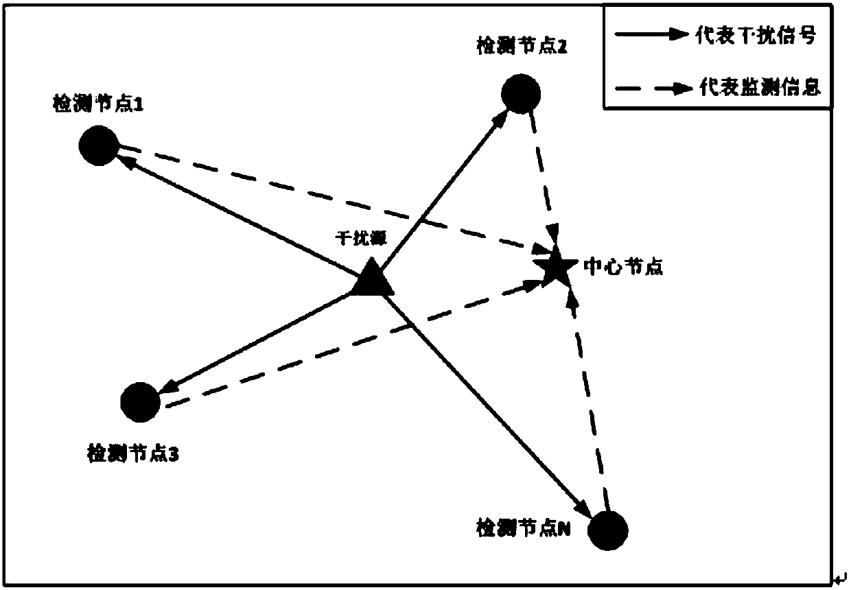
[0050] Embodiment 1. This embodiment discloses a method for locating a gridded GNSS interference source based on a radio wave propagation model. The specific content is as described in the content of the invention, which will not be repeated here. detection and localization. It usually uses 3 or more detection nodes to cover the monitoring area. like figure 1 As shown, each detection node can not only output location information in real time, but also detect whether there is interference in real time.

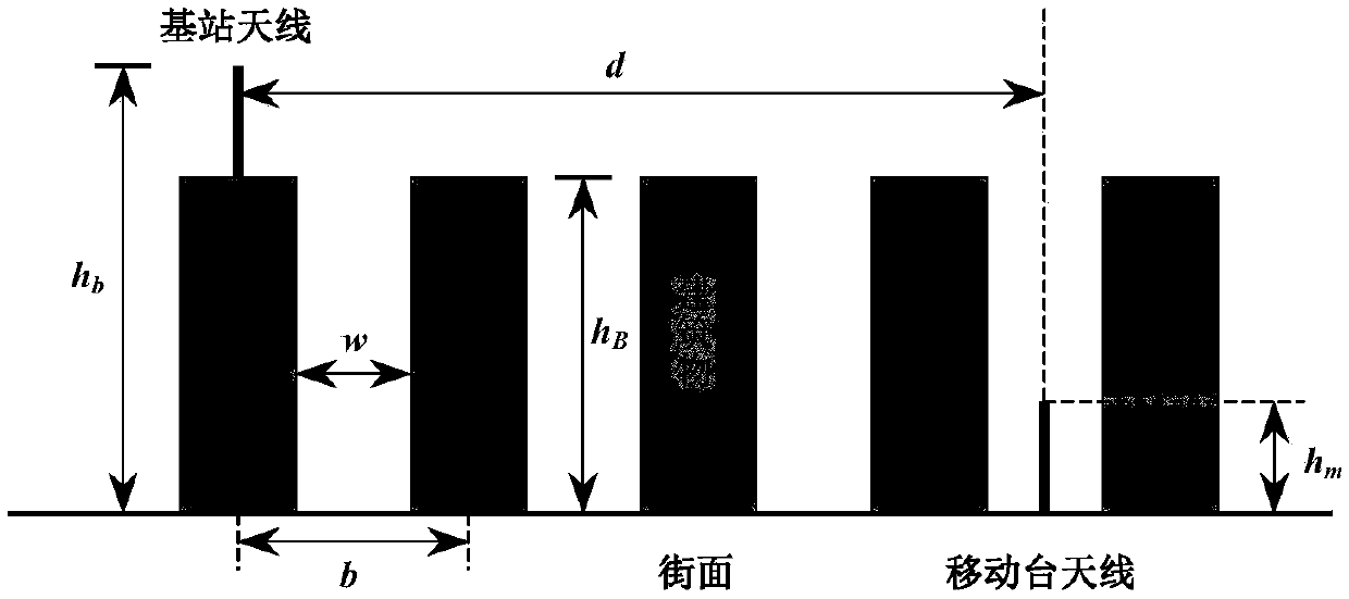
[0051] Because signal propagation is easily affected by topography, including terrain fluctuations, ground vegetation, buildings and other factors. The signal power measured by each node is prone to deviation, and the magnitude of the deviation largely determines the positioning accuracy of the interference source. In this embodiment, an accurate radio wave propagation model is used to correct the signal power, and different correction model parameters can be selected accor...


PUM


Abstract

The invention discloses a GNSS interference source positioning method based on a radio wave propagation model. The method comprises the following steps of: (1) reasonably arranging detection nodes ina monitoring area range; (2) if the detection nodes detect an interference signal with the power exceeding a predetermined threshold, determining that there is interference; (3) receiving and processing the monitoring data sent by each detection node, and analyzing the position of the detection nodes, the power of the received interference signal, and the environment type information, then performing GNSS interference source positioning in combination with the radio wave propagation model by a center node; and (4) after the center node performs the interference source positioning, calculatingthe equivalent radiation power of an interference source by using the radio wave propagation model based on the detection node closest to the interference source. The GNSS interference source positioning method based on the radio wave propagation model adopts the radio wave propagation model applicable to various environments to calculate the losses of signal propagation paths, thereby improving the positioning accuracy of the interference source.

Description

technical field [0001] The invention belongs to the field of electromagnetic interference research, and particularly relates to a method for locating a GNSS signal interference source in the field. Background technique [0002] Satellite navigation has been integrated into various application fields including transportation, surveying and mapping, communication, radar, aviation, and scientific research. GNSS (Global Navigation Satellite System) provides real-time precise position, speed and time information to countless users on land, sea, air and space around the world. However, due to the increasingly complex electromagnetic environment, intentional or unintentional interference, and the vulnerability of satellite signals themselves, satellite navigation signals are susceptible to interference. [0003] Once the GNSS signal is interfered, it will not only affect the normal life of ordinary users, but also seriously affect the key infrastructure closely related to national...

Claims


Application Information

Patent Timeline
IPC IPC(8): G01S19/21G01S19/42H04B17/345
CPCH04B17/318H04B17/345G01S19/21G01S19/42Y02D30/70
Inventor 张风国陈奇东甄卫民车磊
Owner 中国电波传播研究所
Learn More