Soil in-situ leaching remediation method

A soil and leaching technology, applied in the field of soil in-situ leaching and remediation, can solve the problems of insufficient contact between the eluent and pollutants, poor leaching and remediation effect, and limited radiation range of shafts, etc. Effects and Rates, Enhanced Repair Effects, Simple Structured Effects

Inactive Publication Date: 2019-04-05
安徽国祯环境修复股份有限公司
View PDF8 Cites 9 Cited by
  • Summary
  • Abstract
  • Description
  • Claims
  • Application Information

AI Technical Summary

Problems solved by technology

[0003] The existing soil in-situ leaching repair methods have certain disadvantages in use. At present, the in-situ leaching technology mostly uses shafts to inject eluent, but affected by factors such as soil permeability coefficient, the radiation range of shafts is limited. , the eluent cannot fully contact with the pollutants, and the effect of leaching repair is poor; in other invention patents, horizontal wells are used for eluent injection. This method can increase the contact area between the eluent and pollutants and improve However, the construction of horizontal wells requires large-scale excavation of the soil and laying pipes. The construction is difficult, the process is complicated, the amount of work is large, and the restoration effect is not good, and the restoration time is relatively long. Therefore, we propose a Soil in-situ leaching and remediation method

Method used


Image

  • Soil in-situ leaching remediation method
  • Soil in-situ leaching remediation method
  • Soil in-situ leaching remediation method

Examples


Embodiment 1

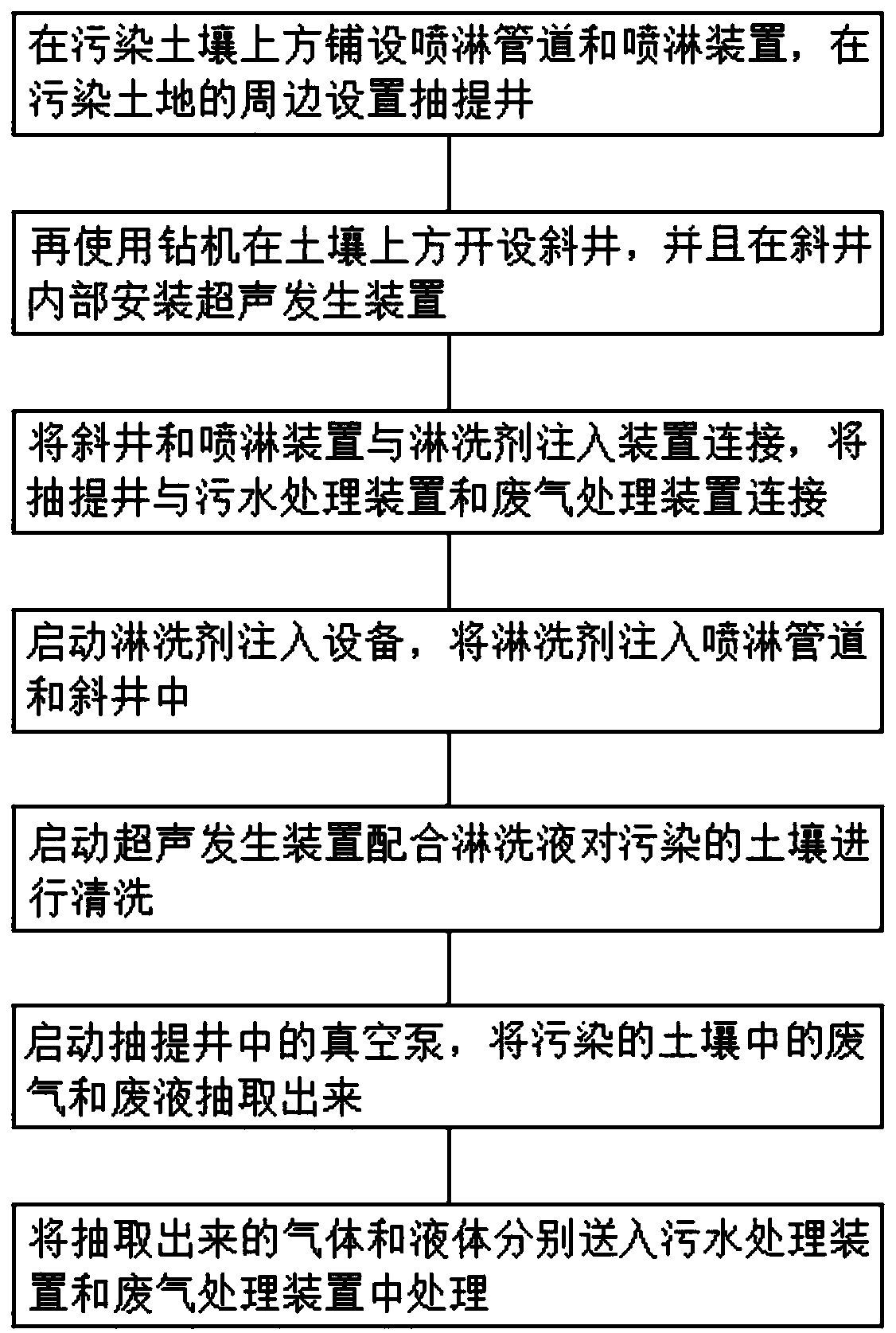
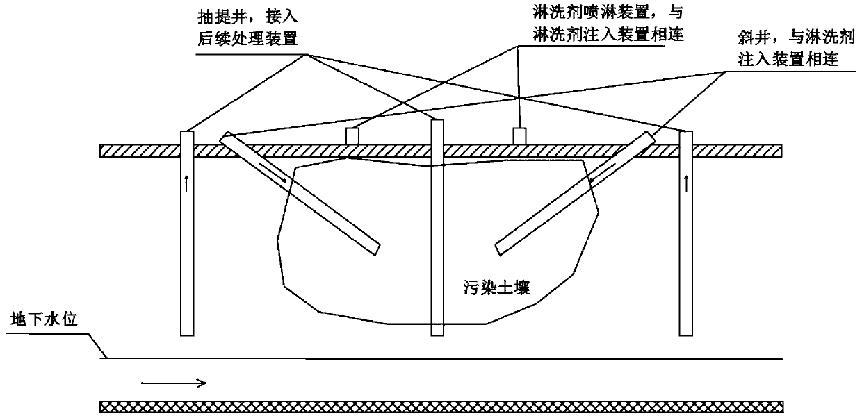
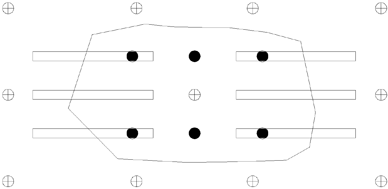
[0029] (1), lay sprinkler pipeline and shower device above the polluted soil, then set extraction well around and in the middle of the polluted soil, sprinkler pipeline and shower device are erected at 40cm above the ground, spray The device adopts high-pressure rotary nozzles, and a high-pressure rotary nozzle is installed every 10 square meters. The diameter of the extraction well is 20mm, and the depth of the well is 3.5 meters. The bottom of the extraction well is set in the soil 1.5 meters away from the groundwater. Set one every 12 square meters;

[0030] (2), use drilling rig again to offer inclined well above polluted soil, and install ultrasonic generating device inside inclined well, set an inclined well every 5 square meters, the inclination angle of inclined well is 45 °, ultrasonic generating device is set The inside of the inclined shaft is 1.0 meters away from the bottom, and the inclined shaft is symmetrically arranged in the polluted soil. The processing diffi...

Embodiment 2

[0037] (1), lay sprinkler pipeline and shower device above the polluted soil, then set extraction well around and in the middle of the polluted soil, sprinkler pipeline and shower device are erected at 40cm above the ground, spray The device adopts high-pressure rotary nozzles, and a high-pressure rotary nozzle is installed every 10 square meters. The diameter of the extraction well is 20mm, and the depth of the well is 3.5 meters. The bottom of the extraction well is set in the soil 1.5 meters away from the groundwater. Set one every 12 square meters;

[0038] (2), use drilling rig again to offer inclined well above polluted soil, and install ultrasonic generating device inside inclined well, set an inclined well every 5 square meters, the inclination angle of inclined well is 45 °, ultrasonic generating device is set The inside of the inclined shaft is 1.0 meters away from the bottom, and the inclined shaft is symmetrically arranged in the polluted soil. The processing diffi...

Embodiment 3

[0045](1), lay sprinkler pipeline and shower device above the polluted soil, then set extraction well around and in the middle of the polluted soil, sprinkler pipeline and shower device are erected at 40cm above the ground, spray The device adopts high-pressure rotary nozzles, and a high-pressure rotary nozzle is installed every 10 square meters. The diameter of the extraction well is 20mm, and the depth of the well is 3.5 meters. The bottom of the extraction well is set in the soil 1.5 meters away from the groundwater. Set one every 12 square meters;

[0046] (2), use drilling rig again to offer inclined well above polluted soil, and install ultrasonic generating device inside inclined well, set an inclined well every 5 square meters, the inclination angle of inclined well is 45 °, ultrasonic generating device is set The inside of the inclined shaft is 1.0 meters away from the bottom, and the inclined shaft is symmetrically arranged in the polluted soil. The processing diffic...


PUM


Abstract

The invention discloses a soil in-situ leaching remediation method. The soil in-situ leaching remediation method includes steps of laying spray pipelines and spray devices above contaminated soil, then arranging extraction wells at the peripheral edge and in the middle of the contaminated soil and mounting gas exhaust devices at the extraction wells; arranging oblique wells above the contaminatedsoil by drilling machines and mounting ultrasonic generating devices inside the oblique wells. The soil in-situ leaching remediation method has the advantages that the soil in-situ leaching remediation cost can be reduced, diffusion regions of leaching agents can be expanded, and contaminants in the soil and leacheate are wide in contact area; the leaching agents can be driven to be fed into soilparticles, and accordingly great effects can be realized; friction and stirring between the soil particles further can be promoted, the leaching agents can be diffused into soil pores, effects of desorbing the contaminants can be sufficiently realized, accordingly, leaching effects can be accelerated, the leaching rates can be increased, and the soil in-situ leaching remediation method has an excellent use prospect.

Description

technical field [0001] The invention relates to the field of in-situ restoration of soil, in particular to a method for in-situ leaching and restoration of soil. Background technique [0002] With the development of society, people pay more and more attention to the environment. In order to improve the environment and restore the land, people have invented many methods, including the method of in-situ leaching and repairing of soil. Soil remediation technology that directly remediates or treats the contaminated soil directly at the location where the site is polluted has the characteristics of low investment and little impact on the surrounding environment, and has been paid more and more attention by people; [0003] The existing soil in-situ leaching repair methods have certain disadvantages in use. At present, the in-situ leaching technology mostly uses shafts to inject eluent, but affected by factors such as soil permeability coefficient, the radiation range of shafts is...

Claims


Application Information

Patent Timeline
Patent Type & Authority Applications(China)
IPC IPC(8): B09C1/02B09C1/00
CPCB09C1/00B09C1/02B09C2101/00
Inventor 王烁李广兵华进李伟平陈姣夏晓武夏太保
Owner 安徽国祯环境修复股份有限公司
Why Eureka
Try Eureka