Construction method of glass reinforced plastic septic tank

A technology of glass tempering and fiberglass, which is applied in biological sludge treatment, etc., can solve problems such as insufficient contact with feces, easy leakage, and polluted water quality, and achieve enhanced overall structural strength and bearing capacity, enhanced sealing effect, and long service life Effect

Inactive Publication Date: 2019-04-05
贵州建工安顺建筑工程有限公司
View PDF3 Cites 0 Cited by
  • Summary
  • Abstract
  • Description
  • Claims
  • Application Information

AI Technical Summary

Problems solved by technology

[0002] Traditional brick and reinforced concrete septic tanks have poor corrosion resistance, long on-site construction period, poor treatment effect, high cost, easy to leak, and occupy a large area
At present, there are plastic septic tanks on the market. This kind of septic tank has strong corrosion resistance and can be industrialized. However, whether it is a brick, reinforced concrete structure or plastic structure, the septic tank mainly releases and intercepts the feces. After natural aging, only relying on its own anaerobic bacteria to react in the anaerobic layer at the bottom of the pool, the contact between the anaerobic bacteria and the feces in the sewage is not sufficient, so there is still a large amount of feces in the discharged water. Discharge into rivers to pollute water quality
FRP septic tanks are also used in the prior art, but most of the FRP are connected by bolts during installation. With the prolongation of use time, the bolts are prone to aging and rusting, causing septic tanks to leak and causing environmental pollution

Method used


Image

  • Construction method of glass reinforced plastic septic tank
  • Construction method of glass reinforced plastic septic tank

Examples


Embodiment Construction

[0024] The technical scheme of the present invention will be further described below in conjunction with the accompanying drawings, but the required protection scope is not limited to the description;

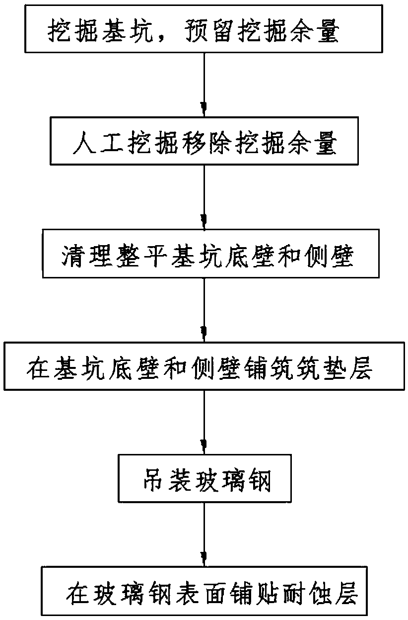
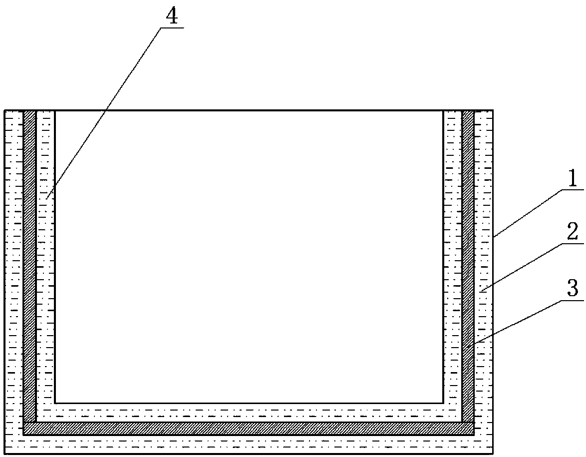
[0025] The invention provides a method for building a glass reinforced plastic septic tank, such as figure 1 , figure 2 shown, including the following steps:

[0026] Step 1: Excavate the foundation pit 1 on the ground, and reserve an excavation margin of appropriate depth at the bottom of the foundation pit 1; further, preferably, the depth of the foundation pit 1 is 0.8m-2m. The excavation allowance depth is 20cm.

[0027] Step 2: Use the method of manual mining to excavate and remove the excavation margin in step 1;

[0028] Step 3: Remove all stones within the foundation pit 1, level and tamp the bottom wall and side walls of the foundation pit 1; pay special attention to clearing sharp stones and some boulders with sharp edges and corners, so as to avoid damage to the ...


PUM

PropertyMeasurementUnit
thicknessaaaaaaaaaa

Abstract

The invention relates to a construction method of a glass reinforced plastic septic tank. The construction method comprises excavating a foundation pit and reserving an excavation margin, removing theexcavation margin by manual excavation, cleaning and flattening the bottom wall and the side wall of the foundation pit, paving construction cushion layers on the bottom wall and the side wall of thefoundation pit, hoisting glass reinforced plastic and paving an anti-corrosion layer on the surface of the glass reinforced plastic. By adopting the technical scheme of the invention, when the foundation pit is excavated, a two-step method is used for excavation; by setting the corresponding excavation margin, the contour shape of the foundation pit is easy to control and is tightly fitted to thesurface of the glass reinforced plastic; the glass reinforced plastic is bonded to the bottom wall and side wall of the foundation pit through the construction cushion layers, and the anti-corrosionlayer is paved on the surface of the glass reinforced plastic. The construction method is favorable for industrial production and convenient to mount; the glass reinforced plastic is firmly installed,so that the overall structural strength and carrying capacity of the septic tank are enhanced. Meanwhile, construction cushion layers and the anti-corrosion layer enhance the sealing effect of the septic tank, avoid pollution caused by exposure of excrements and allow the septic tank to have longer service life.

Description

technical field [0001] The invention belongs to the technical field of septic tanks, in particular to a method for constructing a glass reinforced plastic septic tank. Background technique [0002] Traditional brick and reinforced concrete septic tanks have poor corrosion resistance, long on-site construction period, poor treatment effect, high cost, easy to leak, and occupy a large area. At present, there are plastic septic tanks on the market. This kind of septic tank has strong corrosion resistance and can be industrialized. However, whether it is a brick, reinforced concrete structure or plastic structure, the septic tank mainly releases and intercepts the feces. After natural aging, only relying on its own anaerobic bacteria to react in the anaerobic layer at the bottom of the pool, the contact between the anaerobic bacteria and the feces in the sewage is not sufficient, so there is still a large amount of feces in the discharged water. Discharge into rivers to pollute...

Claims


Application Information

Patent Timeline
Patent Type & Authority Applications(China)
IPC IPC(8): C02F11/04
CPCC02F11/04
Inventor 罗昕胡涛余万江毛华祥黄章鸿帅磊何灿夏良军
Owner 贵州建工安顺建筑工程有限公司
Why Eureka
Try Eureka