
Residual heat recycling device

A waste heat recovery and heat collecting tube technology, which is used in waste heat treatment, transportation and packaging, lighting and heating equipment, etc., can solve the problems of blocking smoke, inconvenient operation, and reduced adsorption performance of the filter, saving energy, simple and convenient operation. , Improve the efficiency of cleaning

Active Publication Date: 2019-04-09
CHONGQING HAOSHENG GLASS
View PDF5 Cites 5 Cited by
  • Summary
  • Abstract
  • Description
  • Claims
  • Application Information

AI Technical Summary

Problems solved by technology

[0004] However, since the heat collecting pipe is arranged in the smoke exhaust pipe, the heat collecting pipe occupies part of the space in the smoke exhaust pipe, the gap between the smoke exhaust pipe and the heat collecting pipe is small, and the flue gas contains a large amount of smoke and dust. It will block the gap between the heat collecting pipe and the smoke exhaust pipe, thereby hindering the normal flow of smoke, and even the smoke blocking the flow of smoke, the amount of smoke in the smoke exhaust pipe will increase, and there will be a risk of explosion
[0005] For this reason, there is a filter screen in the smoke exhaust pipe, but the filter screen has been used for a long time, and the smoke and dust on the filter screen will increase, thereby affecting the performance of the filter screen, and the adsorption performance of the filter screen is reduced, so it is necessary to regularly check the filter screen. cleaning and maintenance, but the filter screen is located in the exhaust pipe, the space of the smoke exhaust pipe is relatively narrow, and the smoke exhaust pipe needs to be disassembled when repairing, so it is troublesome for workers to clean and maintain the filter screen, and the operation is inconvenient

Method used


Image

  • Residual heat recycling device
  • Residual heat recycling device
  • Residual heat recycling device

Examples


Embodiment Construction

[0027] The following is further described in detail through specific implementation methods:

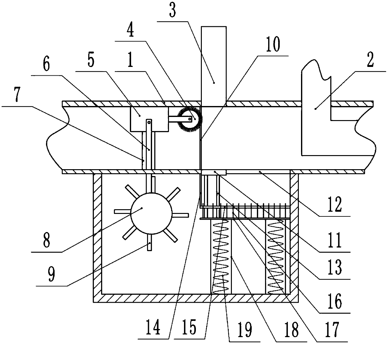
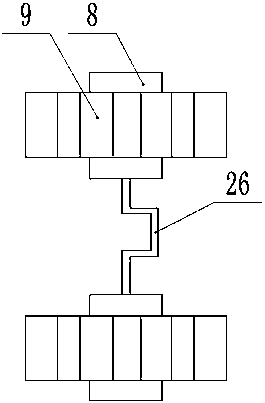
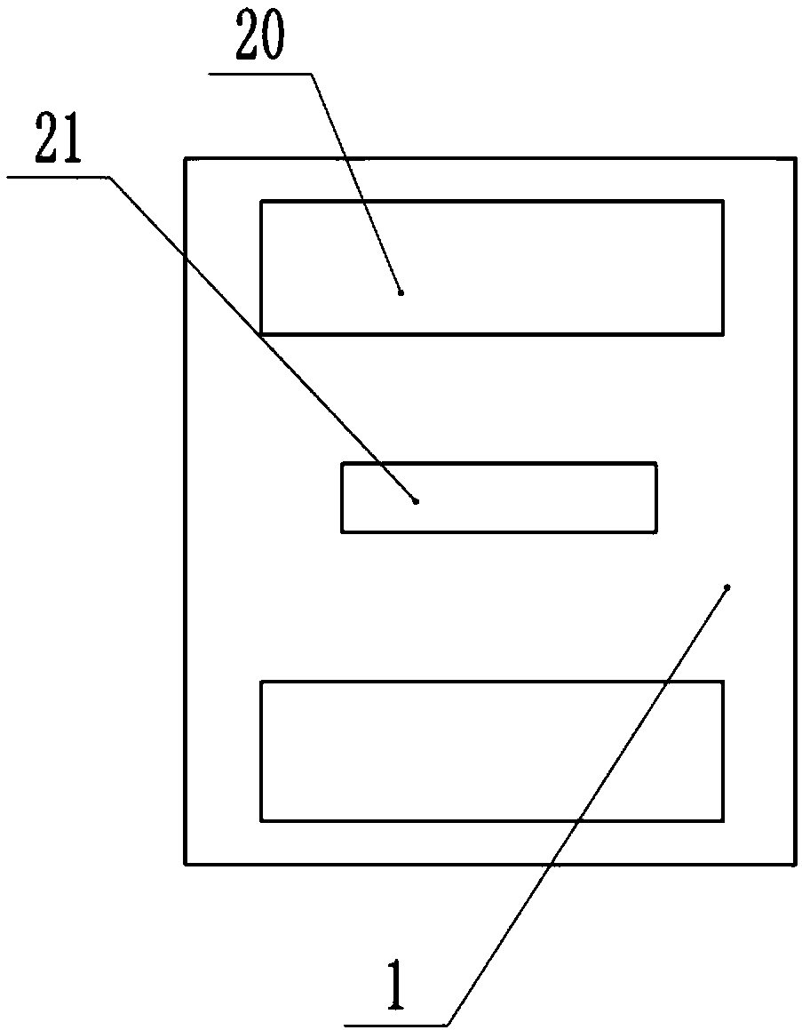
[0028] The reference signs in the accompanying drawings of the specification include: smoke exhaust pipe 1, heat collecting pipe 2, baffle plate 3, cleaning roller 4, slider 5, connecting rod 6, chute 7, rotating roller 8, fan blade 9, main filter screen 10. Press plate 11, air outlet 12, vertical rod 13, fixed plate 14, secondary filter screen 15, plugging needle 16, slide plate 17, telescopic tube 18, pressure spring 19, air inlet 20, connecting rod hole 21, through hole 22, Mesh 23, one-way door 24, torsion spring 25, crankshaft 26.

[0029] The embodiment is basically as attached Figure 1-Figure 5 Shown: the waste heat recycling device, including the exhaust pipe 1 and the heat collecting pipe 2, the heat collecting pipe 2 is located inside the smoke exhaust pipe 1, and the main filter screen 10 located on the left side of the heat collecting pipe 2 is installed in the smoke ex...


PUM


Abstract

The invention relates to the field of glass bottle processing, and particularly relates to a residual heat recycling device. The device comprises a vent pipe, a heat collecting pipe, an ash tank communicated with the vent pipe, an air inlet and an air outlet, wherein the heat collecting pipe is positioned inside the vent pipe; a main filter screen is arranged in the smoke vent; the ash tank is positioned under the vent pipe; a rotary roller opposite to the air inlet is in rotating connection in the ash tank, and is provided with a fan blade; the rotary roller is coaxially connected with a crank shaft; a cleaning mechanism is in sliding connection with the side, far from the heat collecting pipe, of the main filter screen; a connecting rod is connected between the cleaning mechanism and thecrank shaft; two ends of the connecting rod are respectively in rotating connection on the cleaning mechanism and the crank shaft; a secondary filter screen opposite to the air outlet is arranged inthe ash tank; blocking needles are inserted in meshes of the secondary filter screen, and are connected with a press plate which enables the blocking needles to be drawn out from the meshes of the secondary filter screen; and a baffle is in sliding connection with the side, near the heat collecting pipe, of the main filter screen, and can be supported against the press plate.

Description

technical field [0001] The invention relates to the field of glass bottle processing, in particular to a waste heat recycling device. Background technique [0002] Glass bottles are very common in life, such as glass beer bottles, beverage bottles, etc. The production process of glass bottles mainly includes the steps of raw material preprocessing, preparation of batch materials, melting, molding and heat treatment. The melting step refers to placing the glass batch material in a pool kiln or heating it at a high temperature to form a uniform, bubble-free liquid glass that meets the molding requirements. [0003] In the melting process, the combustion of coal is needed to complete the heating. In order to save energy and improve the conversion rate of heat energy, a heat collector is now inserted into the exhaust pipe, and the heat of the flue gas in the exhaust pipe is transferred by heat transfer. The heat collecting tube realizes the reuse of heat energy, and also preve...

Claims


Application Information

Patent Timeline
Patent Type & Authority Applications(China)
IPC IPC(8): B01D46/00F27D17/00
CPCB01D46/10F27D17/004F27D17/008B01D2258/0283B01D46/681Y02P10/25
Inventor 王永杰
Owner CHONGQING HAOSHENG GLASS
Learn More