Draining pump with impeller of small hub ratio

A wheel-to-hub ratio and drainage pump technology, which is applied to parts, pumps, and pump devices of elastic fluid pumping devices, can solve problems such as poor flow capacity of impellers, corrosion of water-passing wall surfaces, rough surfaces, etc., and achieve increased Large flow channel cross-sectional area, improved flow capacity, and excellent hydraulic performance

Pending Publication Date: 2019-04-09
HEFEI UNIV OF TECH
View PDF0 Cites 3 Cited by
  • Summary
  • Abstract
  • Description
  • Claims
  • Application Information

AI Technical Summary

Problems solved by technology

[0002] Traditional dewatering pumps are connected and driven by shafts or similar components, making the device bulky and heavy, hindering the transportation and placement of the device, and bringing about high production costs
Most of the traditional drainage devices have to be placed for a long time before and after use, and the water-passing wall is easily corroded by the liquid trapped in the device, resulting in a decrease in operational stability, and even

Method used


Image

  • Draining pump with impeller of small hub ratio
  • Draining pump with impeller of small hub ratio
  • Draining pump with impeller of small hub ratio

Examples


Embodiment 1

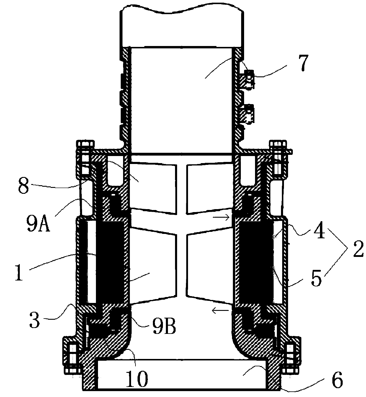
[0073] like figure 1 As shown, a drainage pump with a small wheel-to-hub ratio impeller includes an impeller 1 and a driving part 2 that drives the rotation of the impeller 1. The impeller 1 is a small wheel-to-hub ratio impeller. The drainage pump also includes a housing 3. The drive The part 2 includes a stator assembly 4 fixed on the housing 3, the driving part 2 also includes a rotor assembly 5 cooperating with the stator assembly 4, the rim of the impeller with a small hub ratio is fixedly connected to the inner wall of the rotor assembly 4, And following the rotation of the rotor assembly 4, the small hub is hollow than the middle part of the impeller.

Embodiment 2

[0075] like figure 1 As shown, on the basis of Embodiment 1, the two sides of the housing 3 are respectively provided with a water inlet 6 and a water outlet 7, and the two ends of the rotor assembly 5 are respectively connected with the water inlet 6 and the water outlet 7. The nozzle 7 is provided with a guide vane 8 matching with the impeller 1, and the water passing walls of the casing 3, the rotor assembly 5, and the stator assembly 4 are all provided with anti-corrosion linings using fluorine-lined technology.

Embodiment 3

[0077] like figure 1 As shown, on the basis of Example 2, the rotor assembly 5 is seated in the stator assembly 4 through the wear ring 10, and the upper and lower sides of the rotor assembly 5 are respectively provided with the rotor assembly 5 and the water outlet 7 The outlet-side sliding bearing 9A that cooperates with the rotation and the inlet-side sliding bearing 9B that is convenient for the rotor assembly 5 and the water inlet 6 to rotate in cooperation, the rotor assembly 5, the water outlet 7, the stator assembly 4 and the water inlet 6 are used for The cooling channels for cooling and lubrication are provided with anti-corrosion linings using fluorine-lined technology.


PUM


Abstract

The invention belongs to the field of draining pumps and particularly relates to a draining pump with an impeller of a small hub ratio. The draining pump comprises the impeller and a drive part for driving the impeller to rotate, wherein the impeller has a small hub ratio. The draining pump further comprises a shell. The drive part comprises a stator component fixed on the shell, and a rotor component matched with the stator component. The rim of the impeller of the small hub ratio is fixedly connected with the inner wall of the rotor component, and rotates along with the rotor component. Themiddle of the impeller of the small hub ratio is hollow. The draining pump has the beneficial effects that the impeller of the small hub ratio has reasonable structure and good impeller of the small hub ratio; while the flow and lift meet the requirements of design conditions, the draining pump has the advantages that compared with a traditional structure, the hub size is reduced by about 64%, theexternal diameter of the impeller is reduced by about 13%, the discharge capacity of the impeller is remarkably improved, the sectional area of a runner is enlarged under the condition of the same inlet diameter, and thus the hydraulic efficiency of the draining pump is improved.

Description

technical field [0001] The invention belongs to the field of drainage pumps, in particular to a drainage pump with an impeller with a small hub ratio. Background technique [0002] Traditional drainage pumps are connected and driven by shafts or similar components, making the device bulky and heavy, hindering the transportation and placement of the device, and bringing about high production costs. Most of the traditional drainage devices have to be placed for a long time before and after use, and the water-passing wall is easily corroded by the liquid trapped in the device, resulting in a decrease in operational stability, and even surface roughness or cracks due to metal corrosion on the relative moving surface of the machine. The serious problem that the device cannot be started due to rust residue will greatly reduce the service life of the device. [0003] In addition, the outer diameters of the hub and the impeller of the traditional drainage pump are large, and the vo...

Claims


Application Information

Patent Timeline
IPC IPC(8): F04D13/06F04D29/18F04D29/52F04D29/58H02K7/14G06F17/50
CPCF04D13/0606F04D29/181F04D29/528F04D29/586G06F30/17H02K7/14
Inventor 李强苏晓珍燕浩孟剑柴立平石海峡张羽
Owner HEFEI UNIV OF TECH
Why Eureka
Try Eureka