
Full-automatic line production packaging system

A packaging system, fully automatic technology, applied in the direction of transportation and packaging, continuous processing of textile materials, equipment configuration for processing textile materials, etc., can solve problems such as troublesome handling and waste of time, save time, improve dyeing effect, and improve work efficiency effect

Inactive Publication Date: 2019-04-12
NANTONG GOD OF HORSES THREAD
View PDF9 Cites 3 Cited by
  • Summary
  • Abstract
  • Description
  • Claims
  • Application Information

AI Technical Summary

Problems solved by technology

[0003] The purpose of the present invention is to provide a fully automatic thread-making and packaging system. By setting a dyeing room, an oil immersion room and a setting room, the cotton thread after production will pass through the dyeing room, oil immersion room and setting room in sequence, and the cotton thread will pass through the dyeing room. After dyeing, it is transported to the oil immersion room, and the service life of the cotton thread is improved by soaking in antibacterial liquid, and then the cotton thread enters the setting room, the heating plate in the setting room works to heat the cotton thread, and the electric push rod pushes the first lifting plate to move downward to move the pressing plate Stick to the cotton thread to shape it, and work repeatedly to realize the automatic packaging of the cotton thread after production, improve work efficiency and save time, so as to solve the problem that most of the products in the market are processed by separate equipment, and the handling is troublesome and time-wasting.

Method used


Image

  • Full-automatic line production packaging system
  • Full-automatic line production packaging system
  • Full-automatic line production packaging system

Examples


Embodiment 1

[0023] The present invention provides such as Figure 1-4 A kind of full-automatic line-making packaging system shown, comprises workbench 1, and the top of described workbench 1 is provided with dyeing room 2, and one side of described dyeing room 2 is connected with reflow chamber 3, and the other side of described dyeing room 2 An oil immersion chamber 4 is provided, a shaping chamber 5 is arranged on one side of the oil immersion chamber 4, a cutting table 6 is arranged on the outside of the shaping chamber 5, and a cutting device 7 is fixedly arranged on the top of the cutting table 6, and the cutting device 7 Both sides are provided with a third guide roller 61, the third guide roller 61 is arranged on the top of the cutting table 6, a winding device 8 is provided on one side of the cutting table 6, and a winding device 8 is provided on one side of the winding device 8. Collection chamber 9.

[0024] The interior of the oil immersion chamber 4 is filled with antibacteri...

Embodiment 2

[0028] The inside of the dyeing chamber 2 is evenly provided with a first guide roller 21 , a support plate 22 is provided between the dyeing chamber 2 and the oil immersion chamber 4 , and a hot air blower 23 is evenly provided on the top of the support plate 22 .

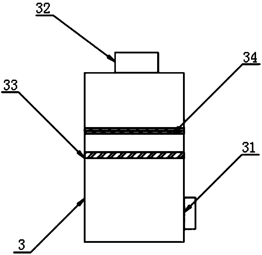
[0029] One side of the return chamber 3 is provided with a switch valve 31, and the top of the return chamber 3 is provided with a water pump 32. The switch valve 31 and the water pump 32 are all communicated with the dyeing chamber 2 through a water pipe, and the inside of the return chamber 3 is provided with A filter screen 33, the top of the filter screen 33 is provided with an activated carbon adsorption layer 34.

[0030] Beneficial effects of this embodiment: open the switch valve 31 and the dyeing solution in the dyeing chamber 2 flows into the return chamber 3, and the water pump 32 works to transfer the dyeing solution back to the dyeing chamber 2, so as to realize the continuous flow of the dyeing soluti...

Embodiment 3

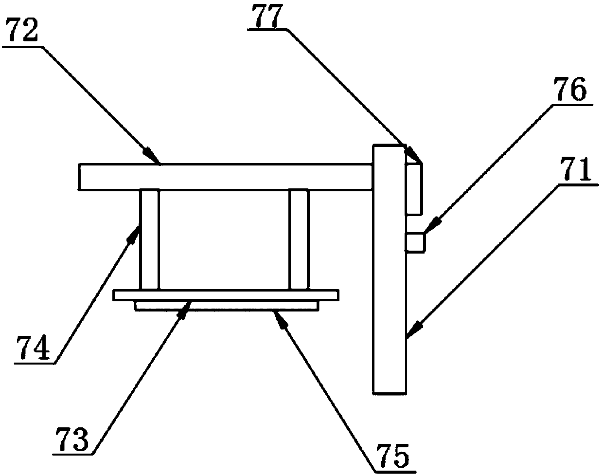
[0032] The cutting device 7 includes a cutting support column 71, a cutting top plate 72, a second lifting plate 73, a hydraulic lifting rod 74, a cutting tool 75, a laser sensor 76 and a buzzer 77, and the cutting support column 71 is arranged on the cutting table 6 At the top, a cutting top plate 72 is fixed on the front side of the cutting support column 71, and a second lifting plate 73 is provided at the bottom of the cutting top plate 72, and a hydraulic lift is evenly arranged between the second lifting plate 73 and the cutting support column 71. A rod 74, a cutting tool 75 is provided at the bottom of the second lifting plate 73, a laser sensor 76 is provided on one side surface of the cutting support column 71, and a buzzer 77 is provided at the top of the laser sensor 76.

[0033]The rewinding device 8 includes a rewinding support column 81, a motor 82, a rotating disc 83 and a rewinding roller 84. The rewinding support column 81 is arranged on the top of the workbenc...


PUM


Abstract

The invention discloses a full-automatic line production packaging system which comprises a working table, wherein a dyeing chamber is arranged at the top of the working table; a backflow chamber is connected with one side of the dyeing chamber; an oil soaking chamber is arranged on the other side of the dyeing chamber; a shaping chamber is arranged on one side of the oil shaking chamber; a cutting platform is arranged on the outer side of the shaping chamber; a cutting device is fixedly arranged at the top of the cutting platform; third guide rollers are arranged on both sides of the cuttingdevice. Due to adoption of the dyeing chamber, the oil soaking chamber and the shaping chamber, a produced cotton line passes through the dyeing chamber, the oil soaking chamber and the shaping chamber in sequence, the cotton line is dyed in the dyeing chamber and is further conveyed into the oil soaking chamber, the service life of the cotton line can be prolonged after soaking with an antibacterial liquid, the cotton line is later fed into the shaping chamber, the cotton line is heated by a heating plate in the shaping chamber, a first lifting plate is pushed by an electronic push rod to move downwards to enable a pressing plate to tightly compress and shape the cotton line, the operation is repeated, then automatic packaging on the produced cotton line can be achieved, the working efficiency can be improved, and the time can be saved.

Description

technical field [0001] The invention relates to the field of cotton thread production equipment, in particular to an automatic thread making and packaging system. Background technique [0002] Cotton thread refers to a slender thread that can be twisted and spun from cotton fiber. As one of the most commonly used daily necessities, cotton thread is used in various fields, especially textiles. With the development of economy, consumers' requirements for cotton thread There are also more requirements. For example, in special industries, cotton thread is required to have wear-resistant, breathable, corrosion-resistant, high-strength and warm-keeping effects. After cotton thread is spun from cotton fibers, subsequent processing and packaging are required to facilitate it. For the next step of product processing, such as dyeing, setting and other processes, most of the current market is processed by separate equipment, which is troublesome and time-consuming to carry. Therefore, ...

Claims


Application Information

Patent Timeline
Patent Type & Authority Applications(China)
IPC IPC(8): D06B21/00D06B3/04D06B23/20D06C7/02D06H7/00B65H63/08
CPCB65H63/082B65H2701/31D06B3/04D06B21/00D06B23/20D06C7/02D06H7/00
Inventor 马志宏
Owner NANTONG GOD OF HORSES THREAD
Learn More