Sliding mold construction device with crane and construction method thereof

A technology of construction equipment and cranes, which is applied in the direction of erecting/assembling bridges, buildings, bridge construction, etc. It can solve the problems of difficult control of formwork verticality, high construction cost, and impact on construction efficiency, so as to improve the poor appearance quality and reduce construction costs. , the effect of improving work efficiency

Pending Publication Date: 2019-04-12
柳州煜乾机械装备有限公司
View PDF7 Cites 1 Cited by
  • Summary
  • Abstract
  • Description
  • Claims
  • Application Information

AI Technical Summary

Problems solved by technology

[0006] 1) During the construction process of the self-elevating walking formwork, the upper clamping formwork is opened, the upper outer formwork is lifted, and the upper clamping formwork is closed. There is always a certain synchronization error in the clamping cylinder, so that the clamping formwork is aligned with the lining. The disturbance of the mold will cause a gap between the lining mold and the concrete surface of the poured concrete, and it is easy to leak grout when pouring the next layer of concrete, which will affect the appearance quality of the concrete;
[0007] 2) The construction method of self-elevating walking formwork relies on auxiliary equipment such as winches, tower cranes and other auxiliary equipment for concrete transportation, pouring, and steel reinforcement and equipment transportation. The construction cost is high, and the construction efficiency is affected and limited by auxiliary equipment;
[0008] 3) The upper clamping template and the lower clamping template use the clamping cylinder to clamp the lining mold. The clamping force is completely controlled by the pressure value set by the hydraulic control system. After clamping the lining mold, the stroke of the clamping cylinder may appear The length is different, and after the formwork is clamped and closed, it is difficult to control and adjust the accuracy of the shape and size of the pier;
[0009] 4) During the lifting process of the lower outer formwork and the upper outer formwork, due to the jacking oil cylinder, there is a synchronization difference between the climbing machine and the formwork formwork is easy to deviate. It is difficult to control the verticality of the formwork only by dropping the plumb line to observe and detect

Method used


Image

  • Sliding mold construction device with crane and construction method thereof
  • Sliding mold construction device with crane and construction method thereof
  • Sliding mold construction device with crane and construction method thereof

Examples


Embodiment 1

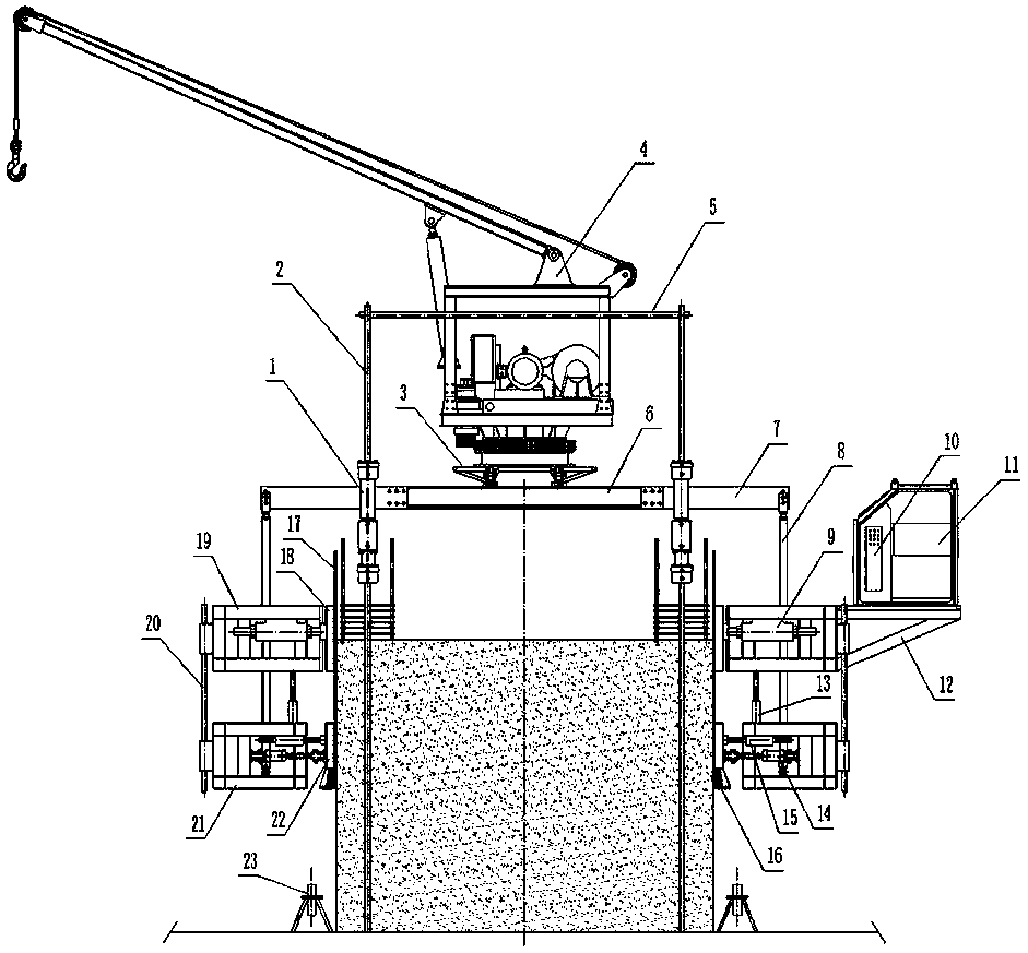
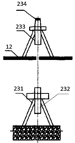
[0063] Such as Figure 1-4 As shown, a slipform construction device with a crane includes a lifting system, a steel structure formwork, a crane 4 and a laser plumb device 23;

[0064] The lifting system includes a jack 1, a hydraulic pump station 11, a control system 10, a jacking cylinder 13 and a clamping cylinder 14; the hydraulic pump station 11 is connected to the jack 1, the jacking cylinder 13 and the clamping cylinder respectively 14 connections; the jack 1 is located on both sides of the top of the concrete seat;

[0065] The control system 10 is connected to a hydraulic pump station 11;

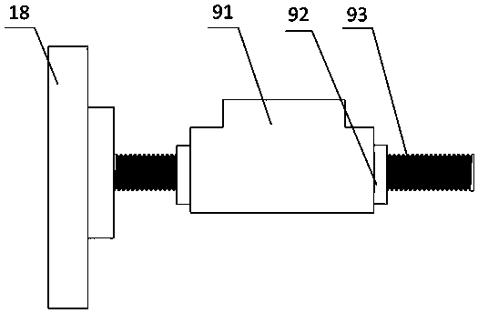
[0066] The steel structure formwork includes a column rod 2, a connecting seat 3, a connecting rod 5, a supporting beam frame 6, a connecting wing plate 7, a boom 8, an adjusting device 9, an operating platform 12, a guiding device 15, a wedge 16, Liner mold 17, sliding formwork 18, upper formwork 19, guide bar 20, lower formwork 21 and clamping formwork 22;

[0067] The column r...


PUM


Abstract

The invention discloses a construction method for a sliding mold construction device with a crane. After one part of concrete of a pier body is poured by a template device and steel bars are tied, aninternal lining mold is installed; a control system controls a hydraulic pumping station to simultaneously push each upper mold base to enable the upper mold base to slide at a predetermined position;during the pushing sliding process, the upper mold bases move alternately; clamping templates clamp the internal lining mold all the time and thus the internal lining mold and concrete surface are relatively stationary, and the sliding templates of the upper mold bases in contact with the internal lining mold can slide longitudinally on the surface; with a laser plummet apparatus, the verticalityof the sliding template device can be detected at any time; after mold adjustment, a release agent is coated, a crane transport concrete for pouring, and after pouring, steel bars are tied and a nextinternal lining mold is installed; and the work is repeated circularly until the pier construction is completed. Therefore, the advantages of fast construction speed and high safety of the sliding mold construction are kept and the defect of the poor concrete appearance quality of the sliding mold construction is overcome.

Description

technical field [0001] The invention relates to construction equipment for a high building pier, in particular to a sliding form construction device with a crane and a construction method. Background technique [0002] Sliding form engineering technology is a kind of construction with high degree of mechanization, fast construction speed, less site occupation, strong structural integrity, good seismic performance, safe operation guarantee, and remarkable comprehensive environmental and economic benefits in the construction of cast-in-place concrete structures in my country. technology. [0003] Application time: 2015.11.26, application number: CN201520962663.1, the utility model discloses a self-elevating walking formwork device for a high building pier, including: a hydraulic lifting system and a formwork system, and the hydraulic lifting system includes a climbing machine , hydraulic pump station, control system, oil pipe, clamping cylinder and jacking cylinder; said formw...

Claims


Application Information

Patent Timeline
Patent Type & Authority Applications(China)
IPC IPC(8): E01D21/00E01D19/02
CPCE01D19/02E01D21/00
Inventor 卢卫平张毅韦贵友
Owner 柳州煜乾机械装备有限公司
Why Eureka
Try Eureka