
Double-impeller horizontal shaft wind turbine design optimization method

An optimization method and horizontal axis technology, applied in design optimization/simulation, wind turbines consistent with the wind direction, wind turbines, etc., can solve problems such as large amount of calculation, low efficiency, and inability to predict the aerodynamic performance of the second-stage impeller , to achieve the effect of improving accuracy and speed and improving design efficiency

Active Publication Date: 2019-04-12
协鑫泛能科技有限公司
View PDF4 Cites 3 Cited by
  • Summary
  • Abstract
  • Description
  • Claims
  • Application Information

AI Technical Summary

Problems solved by technology

The model test research mainly studies the influence of two-stage impeller spacing, two-stage impeller speed matching, and two-stage impeller size on the overall output power of the wind turbine. However, the Reynolds number corresponding to the characteristic size of the wind tunnel test model is very different from the actual wind turbine. The reflected laws are not necessarily applicable to the prototype DRWT, and can only be used as a reference for the design of the prototype DRWT, and there is currently no design method for the prototype DRWT
Aerodynamic performance prediction is the key to wind turbine design. BEMT method (Blade Element Momentum Theory) is mainly used in engineering applications, and the calculation speed is fast, but the second-stage impeller of the actual DRWT cannot work when the first-stage impeller is fully developed. In the wake, BEMT cannot predict the aerodynamic performance of the second-stage impeller of this patent; while the traditional CFD method (Computational Fluid Dynamics, Computational Fluid Dynamics) has a large amount of calculation and low efficiency
In addition, since DRWT is a whole with two-stage impellers coupled to each other, traditional engineering methods cannot realize the engineering optimization design function for the overall coupled design

Method used


Image

  • Double-impeller horizontal shaft wind turbine design optimization method
  • Double-impeller horizontal shaft wind turbine design optimization method
  • Double-impeller horizontal shaft wind turbine design optimization method

Examples


Embodiment Construction

[0033] The present invention will be described in further detail below in conjunction with the accompanying drawings and specific embodiments. Examples of the embodiments are shown in the accompanying drawings, and the specific embodiments described in the following embodiments of the present invention are only illustrative illustrations of specific embodiments of the present invention, and are intended to explain the present invention, rather than constituting a limitation of the invention.

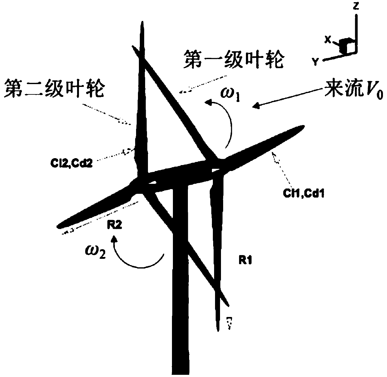
[0034] Two-blade horizontal axis wind turbines, such as figure 1As shown, the radius of the first stage impeller is R 1 , the rotational angular velocity is ω 1 , the pitch angle is θ 1 ;The second-stage impeller radius is R 2 , the rotational angular velocity is ω 2 , the pitch angle is θ 2 ; The distance between the centers of the two-stage impellers is D. The present invention provides a method for optimizing the design of a double-blade horizontal-axis wind turbine, which is u...


PUM


Abstract

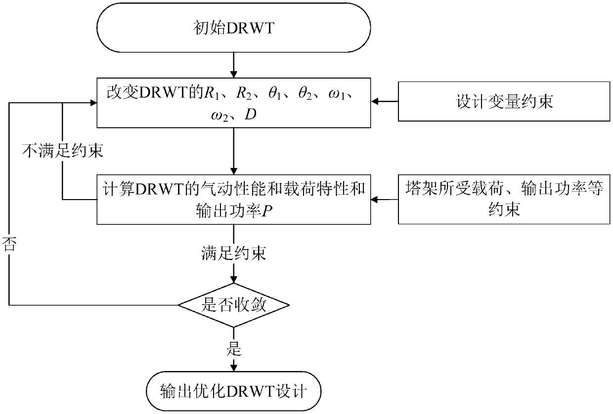
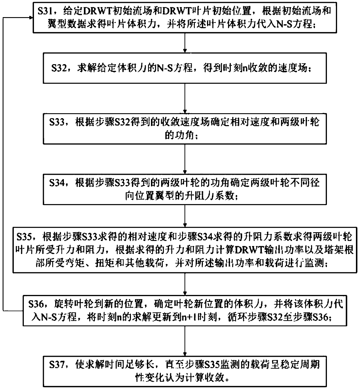
The invention provides a double-impeller horizontal shaft wind turbine design optimization method. The method comprises the following steps: establishing a design optimization model of a DRWT; solvingthe design optimization model of the DRWT; predicting the aerodynamic performance of the DRWT in the process of solving the design optimization model of the DRWT by coupling AL theory and CFD. With the DRWT pitch angle combination, the interval between two stages of impellers, the size of the two stages of impellers and the rotation speed of the two stages of impellers as design variables, the method optimizes the design target with the maximum output power of the DRWT as the optimization design target, and the tower load as the constraint, the AL theory and CFD coupling numerical simulationmethod is proposed for the DRWT model to solve the detailed flow field between the two stage of impellers, so that it is convenient to optimize the design variables; and the method can forecast and evaluate the aerodynamic performance of a double-impeller wind turbine, and can improve the accuracy and velocity of the DRWT aerodynamic performance prediction substantially, thus improving the DRWT design efficiency and laying a foundation for the DRWT engineering design and engineering application.

Description

technical field [0001] The invention relates to a design optimization method, in particular to a design optimization method of a double impeller horizontal axis wind turbine, belonging to the technical field of wind turbines. Background technique [0002] The horizontal axis wind turbine (Horizontal Axis Wind Turbine, HAWT) can be divided into two types: lift type and drag type. For wind power generation, lift-type horizontal axis wind turbines are mostly used. Most horizontal axis wind turbines have a wind-facing device (also known as a yaw system), which can rotate with the change of the wind direction. When the direction of the wind speed vector changes, it can quickly and smoothly align with the wind direction so that the wind rotor can obtain the maximum wind energy; For large wind turbines, the transmission device composed of wind direction sensing elements and servo motors is used, which also constitutes a component of the wind turbine nacelle. [0003] Traditional ...

Claims


Application Information

Patent Timeline
IPC IPC(8): F03D1/02F03D1/06G06F17/50
CPCF03D1/025F05B2260/84G06F30/17G06F2119/06G06F30/20F03D1/0658Y02E10/72
Inventor 徐浩然赵晖梅志刚曹云雪
Owner 协鑫泛能科技有限公司
Learn More