
Fuel gas combustion system suitable for fire tube boiler

A technology of gas combustion and fire tube boilers, which is applied in the direction of gas fuel burners, burners, combustion methods, etc., which can solve the problems of underutilized boiler furnace space, difficulty in achieving ultra-low NOx emissions, and heat transfer effects of fire tube boilers To achieve the effect of excellent stable combustion ability, complete combustion, and less CO

Pending Publication Date: 2019-04-12
SHANGHAI WISEBOND TECH +1
View PDF0 Cites 2 Cited by
  • Summary
  • Abstract
  • Description
  • Claims
  • Application Information

AI Technical Summary

Problems solved by technology

At present, the low-nitrogen burners of fire tube boilers on the market, the gas in the gun head is mostly directly injected towards the furnace ( Figure 5 ), although the flame can spread to the periphery during the subsequent combustion process, some boiler furnace space is still not fully utilized, and the flame is relatively concentrated, resulting in high original NOx emissions; and the use of external flue gas recirculation technology requires external Technical transformation of smoke circulation components
[0004] Although the fire tube boiler has the advantages of saving land and less steel consumption, the heat transfer area of ​​the furnace is smaller than that of the general water tube boiler, the volumetric heat load is high, and the heat transfer effect of the fire tube boiler is worse than that of the water tube boiler. It is more difficult for tube boilers to achieve ultra-low emission of NOx (≤30mg / Nm 3 ), especially some special fire tube boilers, such as central backfire, cast iron and other fire tube boilers

Method used


Image

  • Fuel gas combustion system suitable for fire tube boiler
  • Fuel gas combustion system suitable for fire tube boiler
  • Fuel gas combustion system suitable for fire tube boiler

Examples


Embodiment Construction

[0019] The present invention will be further described below in conjunction with the accompanying drawings and embodiments of the specification.

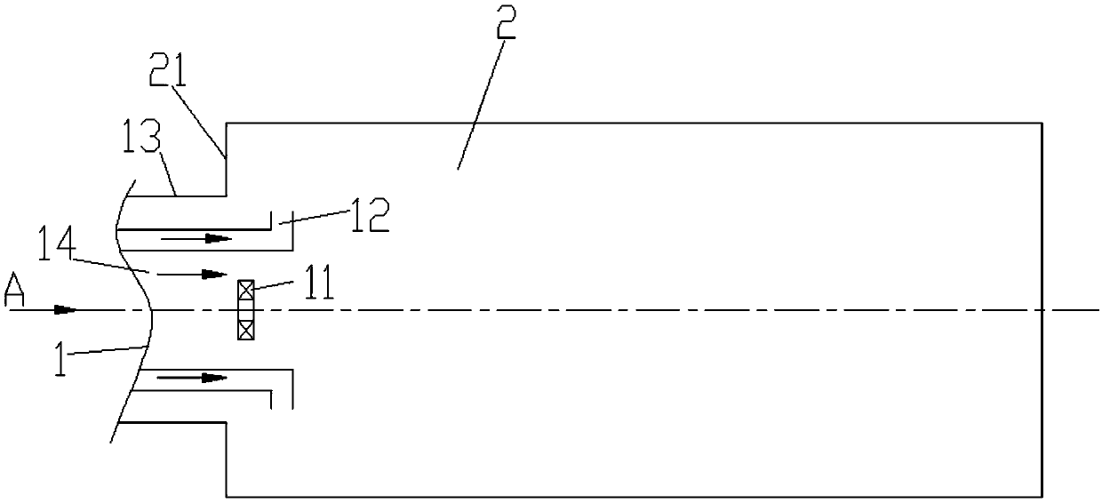
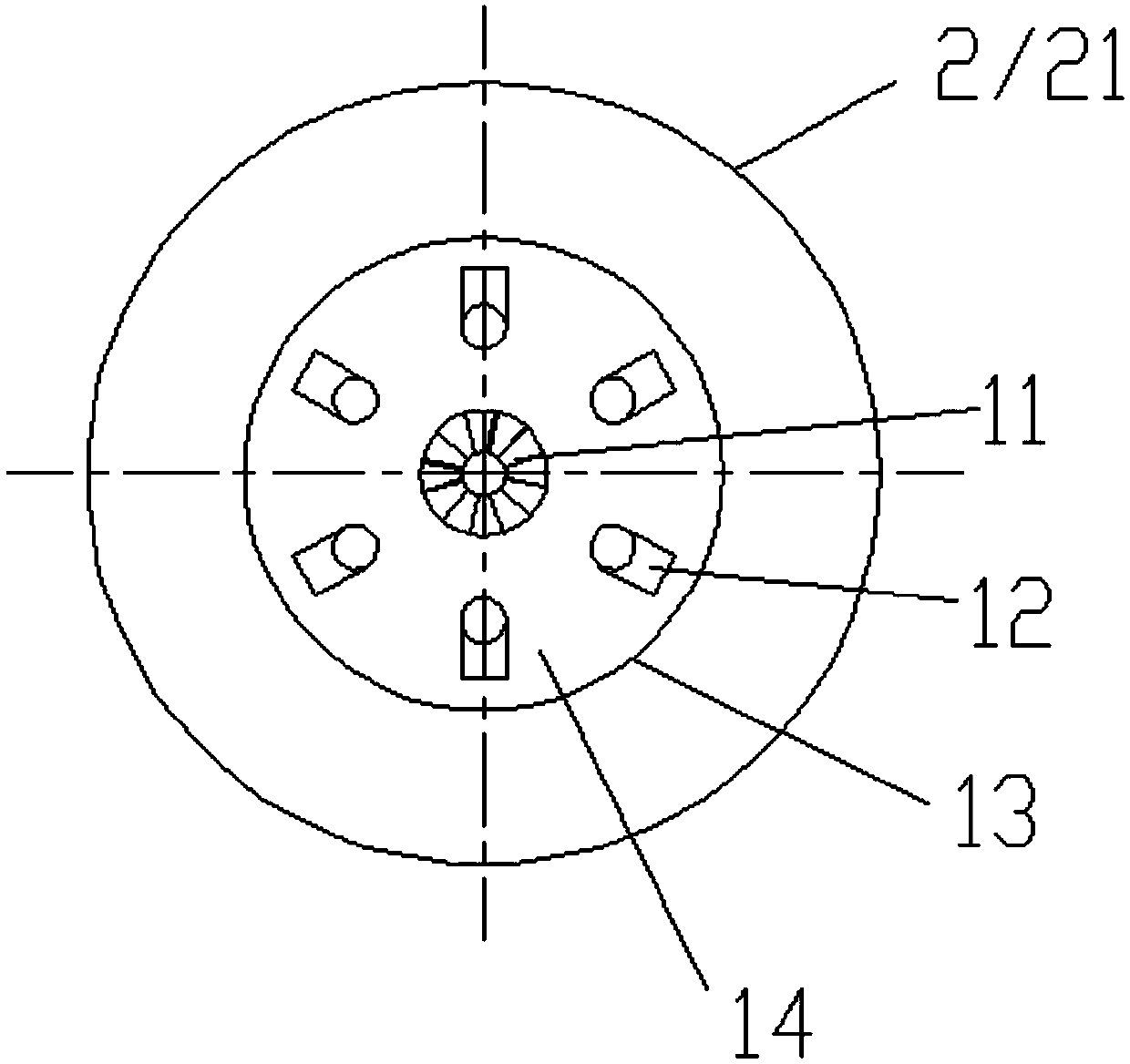
[0020] figure 1 and figure 2 It is a schematic structural diagram of the present invention, and it can be seen from the diagram that a gas combustion system suitable for a fire tube boiler includes a low-nitrogen burner 1 and a boiler furnace 2, and the low-nitrogen burner 1 is arranged on the boiler front wall 21 of the boiler furnace 2; It is characterized in that: the low-nitrogen burner 1 includes a flame stabilization plate 11, a gas gun 12, a burner throat 13 and a combustion air passage 14, and the flame stabilization plate 11, the gas gun 12, the burner throat, and 13 are composed of The central axis of the burner is arranged symmetrically outward in sequence; the combustion air channel 14 is placed in the throat 13 of the burner.

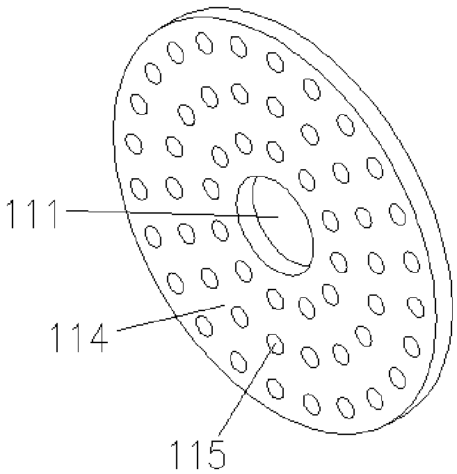
[0021] The main body of the flame stabilizing plate 11 is circular, which is a circular f...


PUM


Abstract

The invention discloses a fuel gas combustion system suitable for a fire tube boiler, relates to the technical field of ultralow nitrogen combustion of gas-fired boilers, and aims to solve the technical problem of effectively reducing the NOx emission concentration of the fire tube boiler. The fuel gas combustion system is characterized in that a few of air guns are arranged in the center of a flame stabilizing disc; a plurality of stable combustion air channels are arranged on the periphery of the flame stabilizing disc; a fuel gas gun is arranged on the outer side of the flame stabilizing disc; and the spray orifice of the fuel gas gun stretches out of the throat of a combustor and is outwards in the radial direction. The fuel gas combustion system has the following advantages: the combustion system has excellent stable combustion capacity; the fuel gas sprays outwards in the radial direction to enlarge the covering range of flame and reduce the flame peak temperature by utilizing the boiler hearth to the maximum; and in addition, exhaust gas recycling is generated in the boiler, so that the recycling usage amount of external exhaust gas is reduced, and 30 mg and even less NOx isdischarged.

Description

technical field [0001] The invention relates to the technical field of ultra-low nitrogen combustion of gas-fired boilers, in particular to a gas combustion system of a fire-tube boiler, which adopts the way of divergent injection of gas from the furnace core to the surrounding space of the furnace to reduce the peak temperature of the flame of the furnace core and achieve the purpose of reducing NOx emissions. Background technique [0002] With the continuous development of our country's economy, the country's requirements for the environment are gradually becoming stricter. We encourage everyone to work together to save energy and reduce consumption, and protect the blue sky. Beijing area implements 30mg / Nm 3 The environmental standards have been more than 2 years, and other regions in the country are also tightening the standard limits to encourage users to carry out low-nitrogen combustion transformation. [0003] Current gas 30mg / Nm 3 The low-nitrogen combustion in th...

Claims


Application Information

Patent Timeline
IPC IPC(8): F23D14/72F23D14/22
CPCF23D14/22F23D14/72
Inventor 徐志斌王秀学徐正贾丹丹刘志军赵乾隆
Owner SHANGHAI WISEBOND TECH
Learn More