A device that uses crude chemical synthesis gas to increase solid waste burnout

A crude synthesis gas and solid waste burnout technology, which is applied in the direction of incinerators, combustion types, combustion methods, etc., can solve the problems of insufficient fuel combustion, high cost of use, increased solid waste burnout, etc., and achieves easy access , low cost, and the effect of increasing the combustion temperature

Active Publication Date: 2021-11-23
HARBIN INST OF TECH
View PDF8 Cites 0 Cited by
  • Summary
  • Abstract
  • Description
  • Claims
  • Application Information

AI Technical Summary

Problems solved by technology

[0007] In order to solve the problem that the fuel in the boiler cannot be fully burned when the burner in the existing boiler is in use, resulting in the generation of a large amount of solid waste and the high cost of use, the present invention proposes a method using chemical rough synthesis Air-increased solid waste burnout device

Method used


Image

  • A device that uses crude chemical synthesis gas to increase solid waste burnout
  • A device that uses crude chemical synthesis gas to increase solid waste burnout
  • A device that uses crude chemical synthesis gas to increase solid waste burnout

Examples


specific Embodiment approach 1

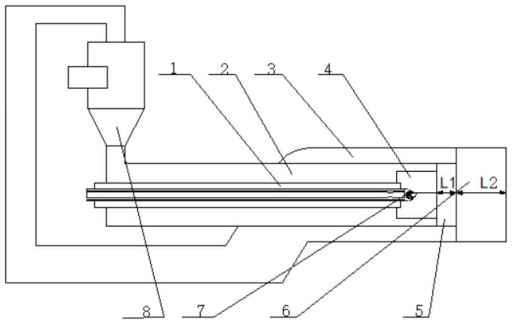
[0026] Specific implementation mode one: combine figure 1 To illustrate this embodiment, a device for increasing solid waste burnout using crude chemical synthesis gas described in this embodiment includes a central chemical crude synthesis gas pipeline 1, a first solid waste air powder pipeline 2, and a second solid waste powder pipeline 3. Primary combustion chamber 4, secondary combustion chamber 5, tertiary combustion chamber 6, ignition gun 7 and cyclone separator 8;

[0027] One end of the second solid waste powder pipe 3 is provided with a three-stage combustion chamber 6, the outer surface of the second solid waste powder pipe 3 is provided with a through hole, and the first solid waste air powder pipe 2 is inserted inside the through hole , the inside of the first solid waste air powder pipeline 2 is provided with a primary combustion chamber 4 and a secondary combustion chamber 5 in sequence from left to right, and an input port is provided on the upper surface of th...

specific Embodiment approach 2

[0030] Specific implementation mode two: combination figure 1 Describe this embodiment. This embodiment is a further limitation on the combustion device described in Embodiment 1. In this embodiment, a device that uses chemical crude synthesis gas to increase solid waste burnout, the first-stage Combustion chamber 4, secondary combustion chamber 5 and tertiary combustion chamber 6 are arranged coaxially.

specific Embodiment approach 3

[0031] Specific implementation mode three: combination figure 1 Describe this embodiment. This embodiment is a further limitation on the combustion device described in Embodiment 2. In this embodiment, a device that uses chemical crude synthesis gas to increase solid waste burnout, the first-stage Combustion chamber 4, secondary combustion chamber 5 and tertiary combustion chamber 6 are arranged in communication.


PUM


Abstract

The invention relates to a device for increasing the burnout of solid waste by adopting chemical crude synthesis gas, which relates to the field of boiler burners. In order to solve the problem that the fuel in the boiler cannot be fully burned when the burner in the existing boiler is in use, resulting in a large amount of solid waste and high cost of use. One end of the second solid waste powder pipe is provided with a three-stage combustion chamber, the outer surface of the second solid waste powder pipe is provided with a through hole, and the first solid waste air powder pipe is inserted inside the through hole, and the first solid waste powder pipe is inserted into the through hole. The inside of the exhaust powder pipeline is provided with a primary combustion chamber and a secondary combustion chamber. The other end of the second solid waste powder pipeline is connected to the input port of the cyclone separator, and the output port of the cyclone separator is connected to the first solid waste powder pipeline. The input port on the upper surface of the ignition gun is connected to the input port on the upper surface. After the ignition end of the ignition gun passes through the interior of the first solid waste air powder pipeline, it extends into the interior of the primary combustion chamber. . The invention is applicable to the field of boiler burners.

Description

technical field [0001] The invention relates to the field of boiler burners, in particular to a device for increasing the burnout of solid waste by using crude chemical synthesis gas. Background technique [0002] Since my country is a country rich in coal, low in oil, and poor in gas, coal will still occupy a major position in my country's primary energy consumption for a long time to come. At present, about 670 million tons of coal are directly used for combustion in my country every year, causing environmental pollution. Coal gasification is one of the effective methods to realize efficient and clean utilization of coal. A large amount of solid ash is produced during the gasification process of the gasifier. The solid waste ash contains residual carbon and mineral ash. The treatment methods of burial and accumulation cause energy waste and serious soil pollution, and pose a huge threat to human health. . [0003] Due to the unique fluid dynamic characteristics and stru...

Claims


Application Information

Patent Timeline
Patent Type & Authority Patents(China)
IPC IPC(8): F23G5/02F23G5/12F23G5/16F23G5/44F23J15/02
CPCF23G5/02F23G5/12F23G5/16F23G5/44F23G2202/103F23G2204/103F23G2209/30F23J15/027F23J2217/40
Inventor 陈智超李佳伟袁琳璇李连铠曾令艳李争起
Owner HARBIN INST OF TECH
Why Eureka
Try Eureka