A microwave-ultrasonic coupling cavity suitable for liquid materials

A technology of microwave ultrasonic and coupled cavity, which is applied in the field of microwave-ultrasonic coupled cavity to reduce the risk of electromagnetic wave reflection, ensure safety performance, and improve the effect of treatment

Active Publication Date: 2020-12-29
JIANGNAN UNIV +1
View PDF7 Cites 0 Cited by
  • Summary
  • Abstract
  • Description
  • Claims
  • Application Information

AI Technical Summary

Problems solved by technology

[0004] Although both microwave treatment and ultrasonic treatment have certain application examples and the synergistic effect of the two has been initially explored by scholars, the current microwave-ultrasonic coupling technology is mostly used in the reaction and extraction process of substances.
There are few related studies on the microwave-ultrasonic coupling treatment of continuous flow liquid materials. How to efficiently combine the microwave effect with the ultrasonic cavitation effect is currently a research hotspot in the field of liquid material processing.

Method used


Image

  • A microwave-ultrasonic coupling cavity suitable for liquid materials
  • A microwave-ultrasonic coupling cavity suitable for liquid materials
  • A microwave-ultrasonic coupling cavity suitable for liquid materials

Examples


Embodiment 1

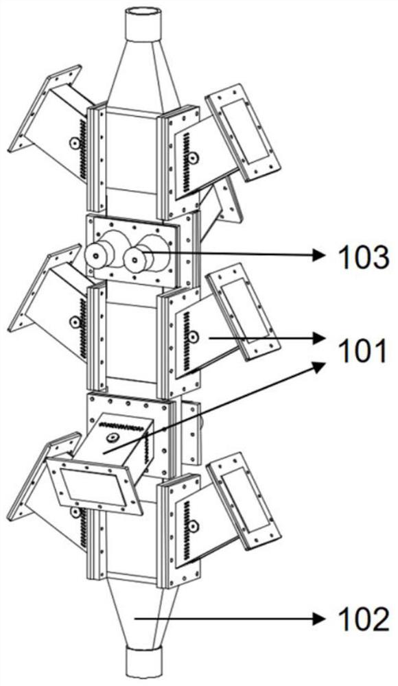
[0030] This embodiment provides a microwave-ultrasonic coupling cavity, please refer to figure 1 , the microwave-ultrasonic coupling cavity includes: a waveguide system 101, a material carrying cavity 102 and an ultrasonic system 103; the cavity of the material carrying cavity 102 includes at least a pair of ultrasonic systems 103 and waveguide systems 101 corresponding to each other, the Each waveguide in the waveguide system 101 is connected to the wall of the material carrying cavity at a predetermined angle, and the predetermined angle is greater than or equal to 15° and less than 90°.

[0031] The ultrasonic system 103 includes at least one ultrasonic generating device. When the ultrasonic system 103 includes more than two ultrasonic generating devices, the ultrasonic generating devices are installed alternately on opposite walls of the material carrying cavity 102 and opposite to the waveguide.

[0032] The predetermined angle range is [30°, 60°].

[0033] The material ...

Embodiment 2

[0051] The microwave-ultrasonic coupling treatment device provided in Example 1 can be used to process fluid substances in the fields of chemical industry, food, and medicine. For example, refer to Image 6 , provides a continuous microwave-ultrasonic coupling sterilization equipment that uses the microwave-ultrasonic coupling cavity to carry out microwave-ultrasonic coupling sterilization of fluid materials. The microwave-ultrasonic coupling sterilization equipment includes: feed preheating section 201, microwave-ultrasonic Coupling processing device 202, constant temperature sterilization section 203 and cooling receiving section 204;

[0052] First, in the preparation stage for the use of the continuous microwave-ultrasonic coupling processing equipment, use the network analyzer to adjust the position of the adjuster in the waveguide system by measuring the S11 parameter and voltage standing wave ratio, so that it can play the expected role; then check the equipment Whether...


PUM


Abstract

The invention discloses a microwave-ultrasound coupling cavity applicable to liquid-state material, and belongs to the technical field of microwave processing. The microwave-ultrasound coupling process taking a microwave effect as main and an ultrasound effect as auxiliary can be achieved by an arrangement mode of a microwave device and an ultrasound device, the electromagnetic wave reflection risk during the process of heating the liquid-state material is reduced to a great extent by a unique waveguide arrangement design of the microwave-ultrasound coupling cavity and by matching a distributor, the running safety of equipment is ensured, meanwhile, an electromagnetic field in a material bearing cavity is more uniform in distribution, the microwave heating cold point is reduced, the microwave effect and an ultrasound cavitation effect are efficiently combined, the processing effect of the liquid-state material is further improved, and the microwave-ultrasound coupling process is achieved.

Description

technical field [0001] The invention relates to a microwave-ultrasonic coupling cavity suitable for liquid materials, belonging to the technical field of microwave processing. Background technique [0002] Microwave refers to electromagnetic waves with a frequency range between 300MHz and 300GHz. In addition to being widely used in the field of communication technology, the heating properties of microwaves on dielectric substances make them one of the emerging technologies for food thermal processing. Compared with traditional heating methods, the characteristics of microwave heating include: 1. Short time and fast speed; 2. Radiation heating, strong penetration, and it is not easy to cause coking caused by overheating of the tube wall during the treatment process; 3. Strong selectivity , related to the dielectric properties of the material; 4. Less energy consumption, small footprint, high degree of automation; 5. Low cost of equipment and accessories. Therefore, it is of...

Claims


Application Information

Patent Timeline
Patent Type & Authority Patents(China)
IPC IPC(8): H05B6/64H05B6/76H05B6/80
CPCH05B6/647H05B6/76H05B6/80H05B2206/04
Inventor 范大明赵建新高文华杨化宇闫博文张宇皓张灏陈卫
Owner JIANGNAN UNIV
Why Eureka
Try Eureka