
Energy-saving type treatment device for chemical engineering production waste gas

A technology for waste gas treatment device and chemical production, which is applied in combination devices, chemical instruments and methods, dispersed particle separation, etc., can solve the problems of reducing purification effect, affecting purification effect, lack of spray mechanism, etc., to improve purification effect, increase The effect of large contact area and avoidance of backflow

Inactive Publication Date: 2019-04-16
孙鑫
View PDF1 Cites 4 Cited by
  • Summary
  • Abstract
  • Description
  • Claims
  • Application Information

AI Technical Summary

Problems solved by technology

[0005] In order to solve the above technical problems, the present invention provides an energy-saving chemical production waste gas treatment device to solve the problem that the existing chemical production waste gas treatment device lacks a pretreatment mechanism, a large number of dust particles enter the purification tower to affect the purification effect, and the bottom of the purification tower lacks a stirring mechanism , the effective components in the purification liquid precipitate at the bottom of the purification tower, reducing the purification effect, lack of spraying mechanism, waste liquid and purification liquid cannot be fully contacted, affecting the purification effect

Method used


Image

  • Energy-saving type treatment device for chemical engineering production waste gas
  • Energy-saving type treatment device for chemical engineering production waste gas
  • Energy-saving type treatment device for chemical engineering production waste gas

Examples


Embodiment

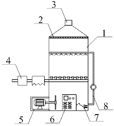
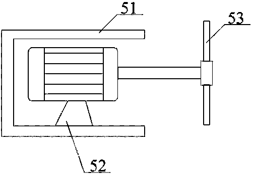
[0025] as attached figure 1 To attach Figure 4 shown

[0026] The present invention provides an energy-saving chemical production waste gas treatment device, which includes a purification tower 1, a filter screen 2, an exhaust port 3, a pretreatment mechanism 4, a stirring mechanism 5, an electrical control cabinet 6, a power cord 7 and a spray mechanism 8, The exhaust port 3 is set at the middle position above the purification tower 1; the filter screen 2 is fixed on the inside of the purification tower 1 by bolts and is located below the exhaust port 3; the electrical control cabinet 6 is fixed on the purification tower 1 by bolts. The middle position of the front end of the tower 1; the power line 7 is embedded in the middle position on the right side of the electrical control cabinet 6, and is connected to the electrical control cabinet 6 through wires; the stirring mechanism 5 is fixed under the left side of the purification tower 1 by bolts ; The pretreatment mechanis...


PUM


Abstract

The invention provides an energy-saving type treatment device for chemical engineering production waste gas. The treatment device comprises a purifying tower, a filter net, a gas discharging port, a pre-treatment mechanism, a stirring mechanism, an electrical control cabinet, a power line and a spraying mechanism. The pre-treatment mechanism, the stirring mechanism and the spraying mechanism are arranged, the waste gas passes through a temperature reducing device and an electric dust moving device to be pre-processed to prevent particles of dust and the like from entering the purifying tower,so that the purifying effect is improved, a motor is controlled by the electrical control cabinet to be electrified and operated to drive stirring blades to rotate to stir effective ingredients whichare precipitated in purifying liquid at the bottom of the purifying tower, so that the purifying effect of the purifying tower is improved, a water pump is controlled by the electrical control cabinetto be electrified and operated to spray out the purifying liquid at the bottom of the purifying tower through a spraying nozzle, the contacting area of the purifying liquid and waste liquid is increased, the purifying effect is improved, the waste gas is delivered through an air inlet pipe, the waste gas is uniformly distributed in the purifying tower through a flow dividing head, so that the waste gas is prevented from gathering in the purifying tower, the purpose of low energy consumption in the purifying process is achieved, which is green and protects the environment.

Description

technical field [0001] The invention belongs to the technical field of waste gas treatment, and in particular relates to an energy-saving chemical production waste gas treatment device. Background technique [0002] A large amount of waste gas will be generated in the chemical production process. In order to make the waste gas meet the environmental protection emission standards, it is necessary to treat the waste gas harmlessly. The usual waste gas treatment method is to pass the waste gas into a certain solution, so that the harmful components in the waste gas are dissolved by the solution. Absorption, but in the existing waste gas treatment equipment, the waste gas stays in the solution for a short time, resulting in poor waste gas treatment effect. [0003] The Chinese patent publication number is CN 207507250 A, and the name of the invention is a chemical waste gas harmless treatment device, which includes a box body, which is filled with a solution for filtering waste ...

Claims


Application Information

Patent Timeline
Patent Type & Authority Applications(China)
IPC IPC(8): B01D53/18B01D53/78B01D53/96B01D50/00
CPCB01D53/18B01D50/00B01D53/78B01D53/96
Inventor 孙鑫
Owner 孙鑫
Learn More