A pod-type full-turn ship electric propulsion system

An electric propulsion and pod-type technology, which is applied in the direction of ship propulsion, rotary propeller, propulsion components, etc., can solve the problems that the diameter of the propeller cannot be changed, the propulsion cannot be obtained, and the propeller cannot reach the speed of the ship. The effect of ship maneuverability, improvement of propeller efficiency, and reduction of electricity cost

Active Publication Date: 2020-10-13
THE FIRST INST OF OCEANOGRAPHY SOA
View PDF16 Cites 0 Cited by
  • Summary
  • Abstract
  • Description
  • Claims
  • Application Information

AI Technical Summary

Problems solved by technology

However, the principle of cavitation is the instantaneous high-speed flow of liquid. The high-speed flow of liquid is caused by the high-speed rotation of the propeller. Therefore, in order to solve the problem of cavitation, it is necessary to reduce the critical speed of cavitation in the propeller, but this is a contradiction. The problem is that if the propeller speed is low, the speed required by the ship cannot be reached, and if the speed is high, cavitation cannot be avoided.
Since the propeller works in the uneven flow field behind the ship, the uneven flow field of seawater causes the thrust and torque generated by the propeller to fluctuate periodically, that is to say, the pulsating force acting on the blade is not a constant Force, therefore adopt CN 105620728 A disclosed propeller capable of variable pitch pitch and CN 104943853 A disclosed propeller capable of variable propeller diameter, which controls the propeller diameter of the propeller according to the size of the centrifugal force of the propeller itself These two technical schemes, Relying on centrifugal force to generate self-drive can not achieve true propeller diameter change, can not obtain stable propulsion, and cannot solve the problem of cavitation caused by changing the propeller diameter to compensate for excessive speed

Method used


Image

  • A pod-type full-turn ship electric propulsion system
  • A pod-type full-turn ship electric propulsion system
  • A pod-type full-turn ship electric propulsion system

Examples


Embodiment Construction

[0020]Below in conjunction with accompanying drawing and specific embodiment the present invention is described in further detail;

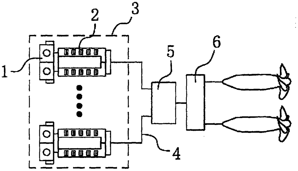
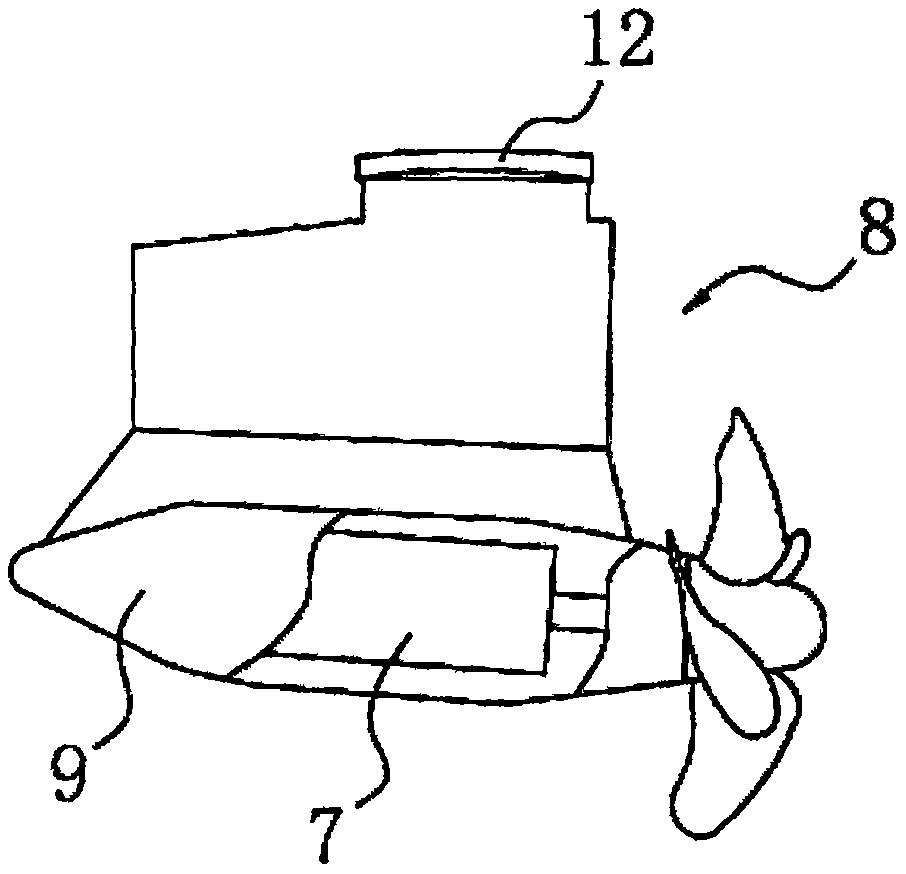
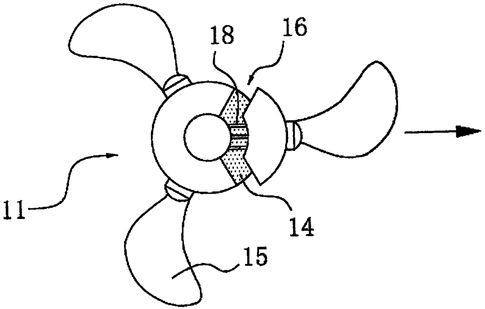
[0021] Such as figure 1 , 2 , 3, 4, and 5, a pod-type full-turn ship electric propulsion system includes at least one group of power generation units 3 composed of a prime mover 1 and a generator set 2 connected to the prime mover 1. In this application, the prime mover 1 is a diesel engine. The diesel engine on board is not used as the main propulsion device, but as the prime mover for generating electricity to drive the motor to generate electricity. They are usually several four-stroke medium-speed diesel engines of the same model and output power. A ship using an all-electric propulsion system can arbitrarily adjust the number of operating generator sets 2 according to changes in the ship's speed, displacement, and electrical load on the ship, so as to maintain high-efficiency operation and reduce fuel consumption. good economy.

[0022] ...


PUM


Abstract

The invention discloses a pod type full-rotation ship electric propulsion system. The system comprises at least one set of power generation unit composed of a prime motor and a generator set connectedwith the prime motor. The electric energy output end of the power generation unit is sequentially connected with a frequency converter and a power output control system through cables, a pod type propeller internally provided with a synchronous motor is connected to the power output control system, a paddle hub is arranged at the end of a propeller shaft, at least two paddles are arranged in theperipheral direction of the paddle hub, and a stretchable mechanism for driving the paddles to stretch out in the direction of the diameter of the paddle hub and a power mechanism driving the stretchable mechanism to move are arranged on the paddle hub. By arranging multiple stretchable components sliding out in the direction of the diameter of the paddle hub on the surface of the paddle hub, thrust of the propeller can be changed by changing the diameter of the propeller, the electricity cost is lowered, the whole service life of the electric propulsion system is prolonged, and the phenomenonof cavitation bubbles is avoided.

Description

technical field [0001] The invention relates to the technical field of ship equipment, in particular to a pod type full-turn ship electric propulsion system. Background technique [0002] The full name of the pod-type electric propulsion system is "permanent magnet motor pod-type full-rotation rudderless propulsion electric propulsion system". Its propulsion motor is not in the hull but underwater, integrated with the propeller, and has no rudder. The entire pod-type propeller can rotate 360° horizontally, just like the vector nozzle used by modern military aircraft engines, the direction of navigation can be adjusted by rotating the direction of the pod, not only can move forward and backward freely, but also can complete "lateral movement Various "difficult movements" such as "turning in place" and "turning in place" have greatly improved the maneuverability and maneuverability of the ship. This propulsion method has high energy conversion efficiency because there is no ...

Claims


Application Information

Patent Timeline
Patent Type & Authority Patents(China)
IPC IPC(8): B63H5/125B63H1/20
CPCB63H1/20B63H5/125B63H2005/1258
Inventor 张志平王立松李欣俞启军张士中孙杨张浩然吕文君殷庆涛
Owner THE FIRST INST OF OCEANOGRAPHY SOA
Why Eureka
Try Eureka