Slag discharging device used for aluminum smelting furnace combustion equipment
A technology for combustion equipment and aluminum smelting furnaces, which is applied to lighting and heating equipment, furnaces, crucible furnaces, etc., can solve the problems of labor-intensive labor and limit the recovery efficiency of aluminum slag, and achieve manpower saving, simple structure, and improved purity Effect
- Summary
- Abstract
- Description
- Claims
- Application Information
AI Technical Summary
Problems solved by technology
Method used
Image
Examples
Embodiment 1
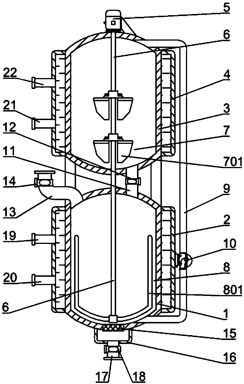
[0032] Such as figure 1 As shown, a slagging device for combustion equipment of an aluminum smelting furnace includes a stirring tank 1, a stirring shaft 6 arranged in the stirring tank 1, a filter screen 15 embedded in the bottom of the stirring tank 1, and a filter screen connected to the lower surface of the stirring tank 1 And cover the collection box 16 of the filter screen 15, and the feeding pipe 13 with the third electric control valve 14 is connected to the stirring tank 1, and the scum in the aluminum smelting furnace enters the stirring tank 1 through the feeding pipe 13 and close the third electronic control valve 14 after the scum enters the stirred tank 1, the lower part of the collection box 16 is connected with the discharge pipe 17 with the fourth electronic control valve 18, and the scum is separated in the stirred tank 1 The aluminum lumps enter into the collection box 16 through the filter screen 15, and the aluminum lumps can be discharged through the disc...
Embodiment 2
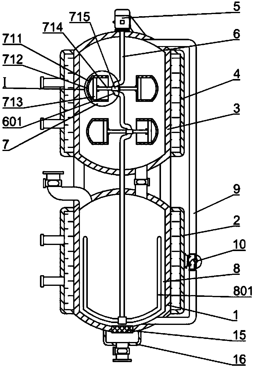
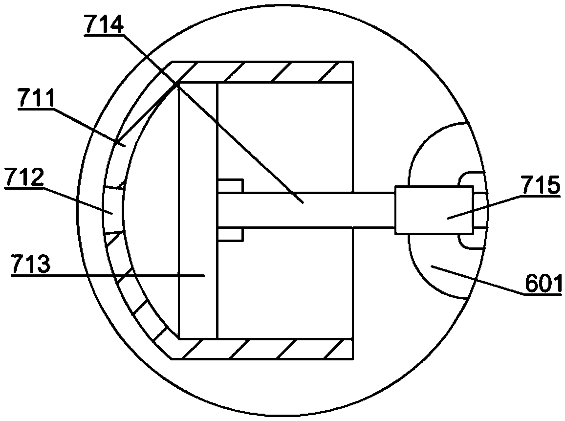
[0039] Such as figure 2 and 3 As shown, the only difference from Embodiment 1 is that the mixing mechanism 7 includes a cylinder 711 arranged in the stirred tank 1, and the cylinder 711 is provided with a spray hole 712 towards the inner wall of the stirred tank 1, and the cylinder 711 A piston 713 is arranged inside, and a connecting arm 714 is hinged on the other side of the piston 713. The stirring shaft 6 has a crankshaft section 601 corresponding to the position of the cylinder body 711, and a sleeve body 715 is rotatably installed on the crankshaft section 601. The connecting arm The other end of 714 is hinged with cover body 715; The rotation of stirring shaft 6 makes crankshaft section 601 rotate, as image 3 As shown, the sleeve body 715 rotates with the crankshaft section 601, and the piston 713 moves back and forth in the cylinder body 711 through the transmission effect of the connecting arm 714, so that the scum mixture is reciprocally sucked into the cylinder b...
Embodiment 3
[0041] On the basis of Example 1, such as Figure 4 As shown, the outside of the stirring tank 1 is provided with a thermal insulation jacket 2, the thermal insulation jacket 2 is connected with a hot oil input pipe 19 and a thermal oil output pipe 20, and the outside of the cooling kettle 3 is provided with a cooling jacket 4 , the cooling jacket 4 is connected with a cold oil input pipe 22 and a cold oil output pipe 21, and also includes a heat pump system, the heat pump system includes a condenser 24 and an evaporator 26, and the condenser 24 and the evaporator 26 pass through two The pipelines are connected, and expansion valves 27 and compression pumps 28 are respectively installed on the two pipelines. The condenser 24 and the evaporator 26 are respectively installed in the heating box 23 and the refrigeration box 25. The heating box 23 and the thermal oil The input pipe 19 is connected with the hot oil output pipe 20, and the second pump body 29 is installed on the hot ...
PUM
 Abstract
Description
Claims
Application Information
 - R&D
- Intellectual Property
- Life Sciences
- Materials
- Tech Scout
- Unparalleled Data Quality
- Higher Quality Content
- 60% Fewer Hallucinations
Browse by: Latest US Patents, China's latest patents, Technical Efficacy Thesaurus, Application Domain, Technology Topic, Popular Technical Reports.
© 2025 PatSnap. All rights reserved.Legal|Privacy policy|Modern Slavery Act Transparency Statement|Sitemap|About US| Contact US: help@patsnap.com


