Position encoder

A technology for encoders and receiving coils, applied in the field of position encoders, can solve problems such as position encoder signal distortion and working environment interference, and achieve the effects of improving reliability, ensuring authenticity, and reducing size

Active Publication Date: 2019-04-16
赛卓电子科技(上海)股份有限公司
View PDF11 Cites 14 Cited by
  • Summary
  • Abstract
  • Description
  • Claims
  • Application Information

AI Technical Summary

Problems solved by technology

[0007] In view of the deficiencies in the prior art, the purpose of the present invention is to provide a position sensor that ...

Method used


Image

  • Position encoder
  • Position encoder
  • Position encoder

Examples


Embodiment Construction

[0044] The present invention will be described in detail below in conjunction with specific embodiments. The following examples will help those skilled in the art to further understand the present invention, but do not limit the present invention in any form. It should be noted that those skilled in the art can make several changes and improvements without departing from the concept of the present invention.

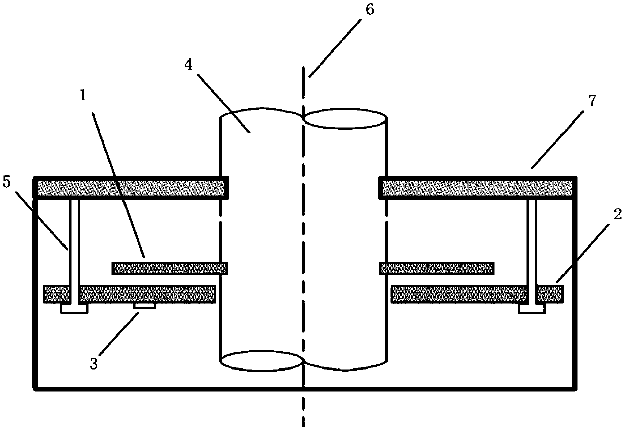
[0045] figure 1 It is a sectional structure diagram of the absolute servo motor position encoder of the present invention.

[0046] like figure 1 As shown, the bearing 4 is installed at the center of the encoder and connected with the encoder housing 7. The bearing rotates synchronously by connecting with the shaft of the external servo motor; the rotor module 1 is fixed on the bearing 4 and rotates with the axis 6; the stator The module 2 is fixed on the encoder housing 7 by screws 5, and the processing circuit 3 is placed on the stator module 2; the rotor module 1 a...


PUM


Abstract

The invention discloses a position encoder. The position encoder comprises a stator module, and the stator module comprises an excitation coil and a receiving coil assembly; the excitation coil is used for conducting high-frequency periodic alternating-current voltage and current, and then generating an alternating electromagnetic field in the region of the stator module; the receiving coil assembly is arranged in the region of the alternating electromagnetic field which is generated by the excitation coil, and the receiving coil assembly can generate induced electromotive force; the positionencoder also comprises a rotor module, and the rotor module is used for influencing electromagnetic coupling strength between the excitation coil and the receiving coil assembly; the position encoderfurther comprises a processing module, and the processing module comprises a signal processing unit and an oscillating circuit unit; and the position encoder further comprises a shielding layer, and the shielding layer is used for shielding outside electromagnetic interference. Compared with the prior art, the position encoder has the advantages that outer interference from metal connecting wires,metal objects, specifically a signal processing module, an electronic component and the like, a motor body and the like can be shielded, so that authenticity of position signals is guaranteed and reliability of the encoder is improved; and absolute-position signals with high precision and high resolution can be provided.

Description


Claims


Application Information

Patent Timeline
Owner 赛卓电子科技(上海)股份有限公司
Why Eureka
Try Eureka