Real-time fluorescence radiation differential super-resolution microscopy method based on parallel spot scanning and device

A real-time fluorescence and super-resolution technology, applied in the field of super-resolution microscopy, can solve the problem of reduced imaging speed and achieve the effect of improving imaging speed

Active Publication Date: 2019-04-16
ZHEJIANG UNIV
View PDF6 Cites 16 Cited by
  • Summary
  • Abstract
  • Description
  • Claims
  • Application Information

AI Technical Summary

Problems solved by technology

However, due to the principle of FED, it requires a positive confocal image and a negative confocal image during imaging

Method used


Image

  • Real-time fluorescence radiation differential super-resolution microscopy method based on parallel spot scanning and device
  • Real-time fluorescence radiation differential super-resolution microscopy method based on parallel spot scanning and device
  • Real-time fluorescence radiation differential super-resolution microscopy method based on parallel spot scanning and device

Examples


Embodiment 1

[0059] A real-time fluorescence radiation differential super-resolution microscopy method based on parallel spot scanning provided in this embodiment includes the following steps:

[0060] (1) After the laser beam emitted by the laser is collimated, it is divided into S polarized light and P polarized light by a polarization beam splitter (PBS);

[0061] (2) Using a quarter-wave plate to modulate the S-polarized light into a circularly polarized solid spot;

[0062] (3) Perform phase modulation on the P polarized light, and modulate it into vortex polarized light;

[0063] (4) Utilizing a quarter-wave plate to further modulate the modulated P-polarized light into a circularly polarized hollow spot;

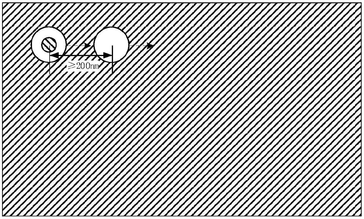
[0064] (5) According to the circular hole diffraction limit formula, in order to ensure that the solid spot and the hollow spot will not interfere with each other, the beam deflection device is used to make the excitation light of the solid spot and the excitation light of the ho...

Embodiment 2

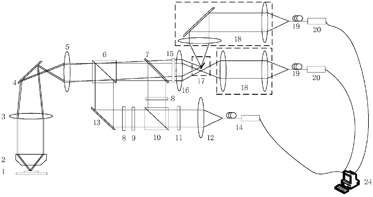
[0072] Such as figure 1 As shown, a real-time fluorescent radiation differential super-resolution microscopy device based on parallel spot scanning provided in this embodiment includes a laser 14, an excitation light modulation optical path sub-module, an object stage 1 carrying a fluorescent sample to be measured, and projecting light to Microscope frame and detection optical path sub-module of stage 1;

[0073] The excitation light modulation optical path sub-module includes:

[0074] A beam expander 12 for expanding the light beam of the point light source emitted by the laser 14 into parallel light;

[0075] A half-wave plate 11 for modulating the polarization direction of the outgoing light from the beam expander 12;

[0076] A polarizing beam splitter 10 for splitting the output light from the half-wave plate 11 into P polarized light and S polarized light;

[0077] A vortex phase plate 9 for performing 0-2π phase modulation on P-polarized light;

[0078] A quarter-w...

Embodiment 3

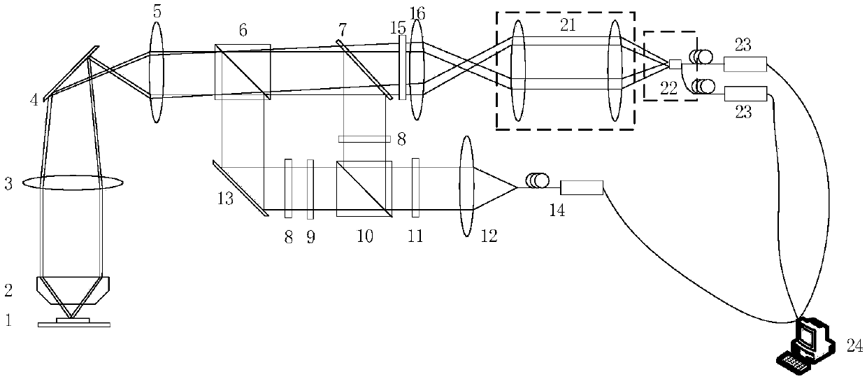
[0097] Such as figure 2 As shown, a real-time fluorescent radiation differential super-resolution microscopy device based on parallel spot scanning provided in this embodiment includes a laser 14, an excitation light modulation optical path sub-module, an object stage 1 carrying a fluorescent sample to be measured, and projecting light to Microscope frame and detection optical path sub-module of stage 1;

[0098] The excitation light modulation optical path sub-module includes:

[0099] A beam expander 12 for expanding the light beam of the point light source emitted by the laser 14 into parallel light;

[0100] A half-wave plate 11 for modulating the polarization direction of the outgoing light from the beam expander 12;

[0101] A polarizing beam splitter 10 for splitting the output light from the half-wave plate 11 into P polarized light and S polarized light;

[0102] A vortex phase plate 9 for performing 0-2π phase modulation on P-polarized light;

[0103] A quarter-...


PUM

PropertyMeasurementUnit
Focal lengthaaaaaaaaaa

Abstract

The invention discloses a real-time fluorescence radiation differential super-resolution microscopy method based on parallel spot scanning and device. In the method, a laser beam is divided to S-polarized light and P-polarized light, the S-polarized light is modulated to a circularly-polarized solid spot, and the P-polarized light is firstly modulated to eddy polarized light and is then modulatedto a circularly-polarized hollow spot; solid spot excitation light and hollow spot excitation light are staggered for at least 200 nm on an object plane; the solid spot excitation light and the hollowspot excitation light are used to perform two-dimensional scanning on a fluorescence sample simultaneously, and a positive confocal fluorescence intensity map obtained by solid spot modulation and anegative confocal fluorescence intensity map obtained by hollow spot modulation are obtained; and the two fluorescence intensity maps are subjected to shift matching. As two spots are adopted for simultaneous scanning, in comparison with the method of switching a modulation spot back and forth by the traditional fluorescence emission differential microscopy system, the sampling speed is more thantwice the traditional speed, the super-resolution dynamic microscopy effects under the confocal scanning speed can be realized, and the imaging speed can be improved significantly.

Description

technical field [0001] The invention belongs to the field of super-resolution microscopy, in particular to a method capable of simultaneously obtaining a positive confocal image modulated by a solid light spot and a negative confocal image modulated by a hollow light spot in the far field, and using a differential method to achieve super-diffraction limit High-resolution super-resolution microscopy method and device. Background technique [0002] The development of fluorescence microscopy has greatly promoted the research in the fields of biological cytology and other fields. However, due to optical diffraction, there is a resolution limit in the conventional far-field optical microscopy method. According to the Abbe diffraction limit theory, the diffraction limit can be determined by the focusing of the objective lens. The full width at half maximum of the light spot is represented, that is, Δr=0.61λ / NA, where λ is the wavelength of light, and NA is the numerical aperture o...

Claims


Application Information

Patent Timeline
IPC IPC(8): G01N21/64
CPCG01N21/6402G01N21/645G01N21/6458G01N2021/6463
Inventor 刘旭张智敏匡翠方徐良李海峰
Owner ZHEJIANG UNIV
Why Eureka
Try Eureka