
A Method of Ultrasonic Echo Signal Extraction Based on Multi-Scale Matching Pursuit

An ultrasonic echo and matching tracking technology, which is applied in the processing of the detected response signal, the use of sonic/ultrasonic/infrasonic waves for material analysis, instruments, etc., can solve the problem of the sparse decomposition algorithm, which requires a large amount of calculation, and the detection accuracy of weak and small defects is limited and cannot be carried out. Real-time detection and other problems, to achieve the effect of simple signal sparse decomposition method, fast signal extraction, and reduced calculation amount

Active Publication Date: 2021-07-13
XIAN UNIV OF SCI & TECH
View PDF4 Cites 0 Cited by
  • Summary
  • Abstract
  • Description
  • Claims
  • Application Information

AI Technical Summary

Problems solved by technology

However, the above-mentioned existing signal extraction methods, such as nonlinear filtering, Fourier transform and wavelet transform, etc., these methods have a good effect on improving the signal-to-noise ratio of general ultrasonic signals, but for small defects or defects under strong noise background The extraction has limitations, the test results are inaccurate, and the reliability is not high
However, the sparse decomposition algorithm has two defects. One is that the sparse decomposition algorithm has a large amount of calculation, and the calculation time is very large under the current computing conditions, so it cannot be detected in real time; the other is that the sparse decomposition algorithm is the optimal solution under continuous conditions. solution, the detection accuracy for weak and small defects is still limited

Method used


Image

  • A Method of Ultrasonic Echo Signal Extraction Based on Multi-Scale Matching Pursuit
  • A Method of Ultrasonic Echo Signal Extraction Based on Multi-Scale Matching Pursuit
  • A Method of Ultrasonic Echo Signal Extraction Based on Multi-Scale Matching Pursuit

Examples


Embodiment Construction

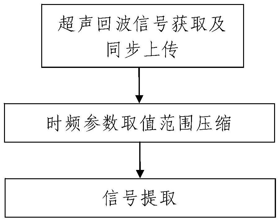
[0105] Such as figure 1 A method for extracting ultrasonic echo signals based on multi-scale matching pursuit is shown, comprising the following steps:

[0106]Step 1. Ultrasonic echo signal acquisition and synchronous upload: use the ultrasonic flaw detection device 1 to perform ultrasonic detection on the object under test, obtain the ultrasonic echo signal F(t) of the object under test, and convert the obtained ultrasonic echo signal f( t) synchronously transmitted to the data processing device 2;

[0107] Among them, f(t)=[f(t 1 ), f(t 2 ),...,f(t N )] T , t represents the time parameter, t i is the i-th sampling moment of the ultrasonic flaw detection device 1, f(t i ) is the signal value sampled at the ith sampling time of the ultrasonic flaw detection device 1, i is a positive integer and i=1, 2, 3, ..., N, N is a positive integer and it is the ultrasonic echo signal f(t) signal length;

[0108] Step 2, time-frequency parameter value range compression: use data ...


PUM


Abstract

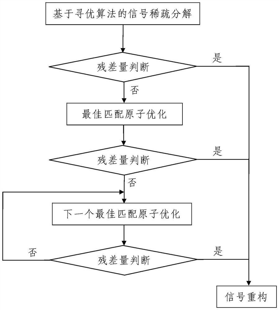
The invention discloses an ultrasonic echo signal extraction method based on multi-scale matching and tracking, comprising the following steps: step 1, ultrasonic echo signal acquisition and synchronous upload; step 2, time-frequency parameter value range compression: using data processing equipment Compress the value range of the time-frequency parameter of the Gabor atom used when the signal to be processed f(t) is sparsely decomposed, and the time-frequency parameter includes a scale parameter, a displacement parameter, a frequency parameter and a phase parameter; Step 3, signal extraction, the process is as follows: step 301. Signal sparse decomposition based on an optimization algorithm; Step 302. Signal reconstruction. The method of the invention has simple steps, reasonable design, convenient implementation, and good use effect. Firstly, the value range of each parameter in the time-frequency parameter is compressed, and then the signal sparse decomposition method based on the optimization algorithm is used to search for the best matching atom. The amplitude speeds up the signal extraction speed and can effectively improve the signal extraction accuracy.

Description

technical field [0001] The invention belongs to the technical field of signal time-frequency analysis, and in particular relates to an ultrasonic echo signal extraction method based on multi-scale matching and tracking. Background technique [0002] Time and frequency are the two most important physical quantities to describe a signal, and there is a close relationship between the time domain and the frequency domain of a signal. Time-Frequency Analysis (JTFA), short for Joint Time-Frequency Analysis, is a powerful tool for analyzing time-varying non-stationary signals and is an emerging signal processing method. The time-frequency analysis method provides the joint distribution information of the time domain (referred to as the time domain) and the frequency domain (referred to as the frequency domain), and clearly describes the relationship of the signal frequency with time. [0003] At present, most of the signals collected by the signal sampling system (also called sign...

Claims


Application Information

Patent Timeline
Patent Type & Authority Patents(China)
IPC IPC(8): G01N29/44
CPCG01N29/4472
Inventor 齐爱玲张广明马宏伟张旭辉曹现刚
Owner XIAN UNIV OF SCI & TECH
Learn More