
All-digital array radar beam former design method based on optical fiber interface

A technology of array radar and optical fiber interface, applied in the design field of all-digital array radar beamformer, can solve the problems of large data transmission pressure, large consumption, long operating distance, etc., to reduce the inconsistency requirements of receiving channels and ensure reliability Effect

Active Publication Date: 2019-04-16
NANJING UNIV OF SCI & TECH
View PDF8 Cites 18 Cited by
  • Summary
  • Abstract
  • Description
  • Claims
  • Application Information

AI Technical Summary

Problems solved by technology

In comparison, the all-digital array radar DBF has a large dynamic range and long operating distance, and can realize multiple beams at the same time, but the all-digital array radar DBF processing needs to consume a lot of hardware multiplier and adder resources, and a large amount of beam data and baseband data need to be transmitted. It will bring a lot of data transmission pressure to the radar signal processor of the subsequent stage

Method used


Image

  • All-digital array radar beam former design method based on optical fiber interface
  • All-digital array radar beam former design method based on optical fiber interface
  • All-digital array radar beam former design method based on optical fiber interface

Examples


Embodiment

[0070] A design method of a fully digital array radar beamformer based on optical fiber interface, the specific steps are as follows:

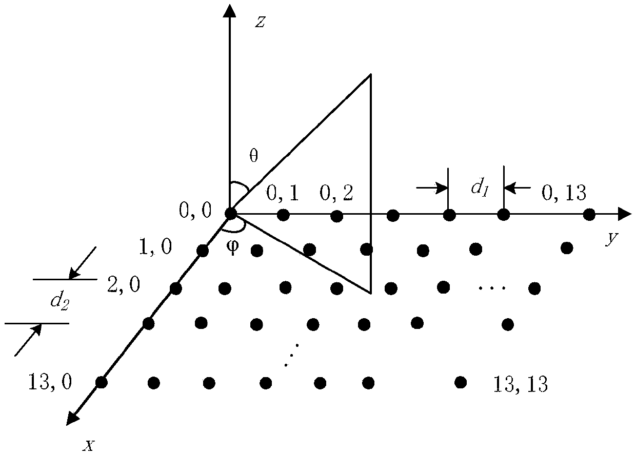
[0071] Such as figure 1 As shown in the two-dimensional planar array, the beamformer input center frequency is 150MHz, the signal bandwidth is 40M intermediate frequency signal, the radar working in discontinuous continuous wave mode, PD mode, LFM mode requires a total of 4 different bandwidth beam data to meet the detection On demand, it is necessary to complete the software radio processing, channel compensation, digital multi-beam forming, data framing transmission and other functions of the 196 element channel intermediate frequency received signal.

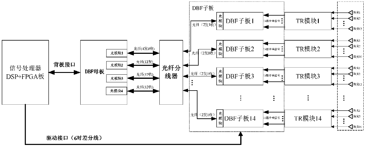
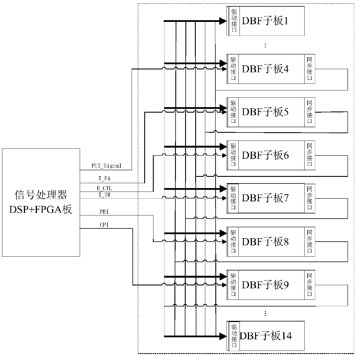
[0072] Step 1. Divide the corresponding relationship of the two-level beamforming architecture. The 14×14 two-dimensional planar array antenna elements are divided into 14 rows, each row corresponds to a first-level DBF daughter board, and each DBF daughter board has 14 sampling channels, 14 piece...


PUM


Abstract

The invention discloses an all-digital array radar beam former design method based on an optical fiber interface, and the method comprises the steps: enabling each row of a two-dimensional planar array antenna array element to correspond to one first-stage DBF daughter board, wherein each first-stage DBF daughter board includes N ADC sampling channels, and M DBF daughter boards are connected withone second-stage DBF mother board; enabling each DBF daughter board to realize software radio processing of corresponding array element intermediate frequency receiving signals to obtain baseband data; calculating an amplitude-phase compensation coefficient of the baseband data of each channel according to the baseband data, then returning the amplitude-phase compensation coefficient to the corresponding DBF daughter board by the DBF mother board to complete amplitude-phase compensation of a receiving channel, and meanwhile completing first-stage digital multi-beam forming according to the self-adaptive weight; and finally, completing second-stage digital multi-beam forming by the DBF mother board according to the first-stage beam forming data. The all-digital array radar digital multi-beam forming function is achieved through the two-stage beam forming framework, data are transmitted through the high-speed optical fiber interface to meet the real-time performance and the stability ofdata transmission, and therefore rapid searching and detecting of airspace targets are met.

Description

Technical field [0001] The invention belongs to the technical field of digital beam forming, and specifically is a design method of a fully digital array radar beam former based on an optical fiber interface. Background technique [0002] With the rapid development of semiconductor integrated circuits and electronic technology, radar technology is also changing with each passing day. In order to adapt to the increasingly complex target environment and electromagnetic environment, the search and detection performance of radar must be greatly improved, and it should have a large dynamic range, multi-waveform, and multi-functional target detection capabilities. Digital array radar adopts digital beamforming (Digital Beamforming, DBF) technology, which has the advantages of large dynamic range and simultaneous formation of digital multi-beams. It can realize rapid target search in a large spatial range. The adaptive DBF algorithm can deal with interference signals in the spatial doma...

Claims


Application Information

Patent Timeline
Patent Type & Authority Applications(China)
IPC IPC(8): G01S7/35
CPCG01S7/35G01S7/352
Inventor 张仁李唐卫平盛卫星马晓峰韩玉兵崔杰赵雨航
Owner NANJING UNIV OF SCI & TECH
Learn More