
A peak-staggered design method for crank-triangular linkage-toggle linkage

A technology of triangular connecting rod and design method, which is applied in the direction of mechanical equipment, forging machine driving device, transmission device, etc. It can solve problems such as analysis and optimization relying on computer simulation, difficulty in finding the global optimal solution, and difficulty in accurate analysis , to achieve the effect of reducing the drive motor capacity, improving the motion characteristics, and increasing the average speed

Active Publication Date: 2021-08-03
GUANGDONG UNIV OF TECH
View PDF4 Cites 0 Cited by
  • Summary
  • Abstract
  • Description
  • Claims
  • Application Information

AI Technical Summary

Problems solved by technology

Due to the complex structure of this mechanism, it is difficult to perform accurate analysis, and the analysis and optimization of the mechanism often rely on computer simulation.
During simulation, the establishment of initial conditions and constraints depends on experience. For such highly nonlinear multi-objective optimization design problems, it is difficult to find the global optimal solution by using heuristic algorithms such as genetic algorithm and simulated annealing algorithm.

Method used


Image

  • A peak-staggered design method for crank-triangular linkage-toggle linkage
  • A peak-staggered design method for crank-triangular linkage-toggle linkage
  • A peak-staggered design method for crank-triangular linkage-toggle linkage

Examples


Embodiment 1

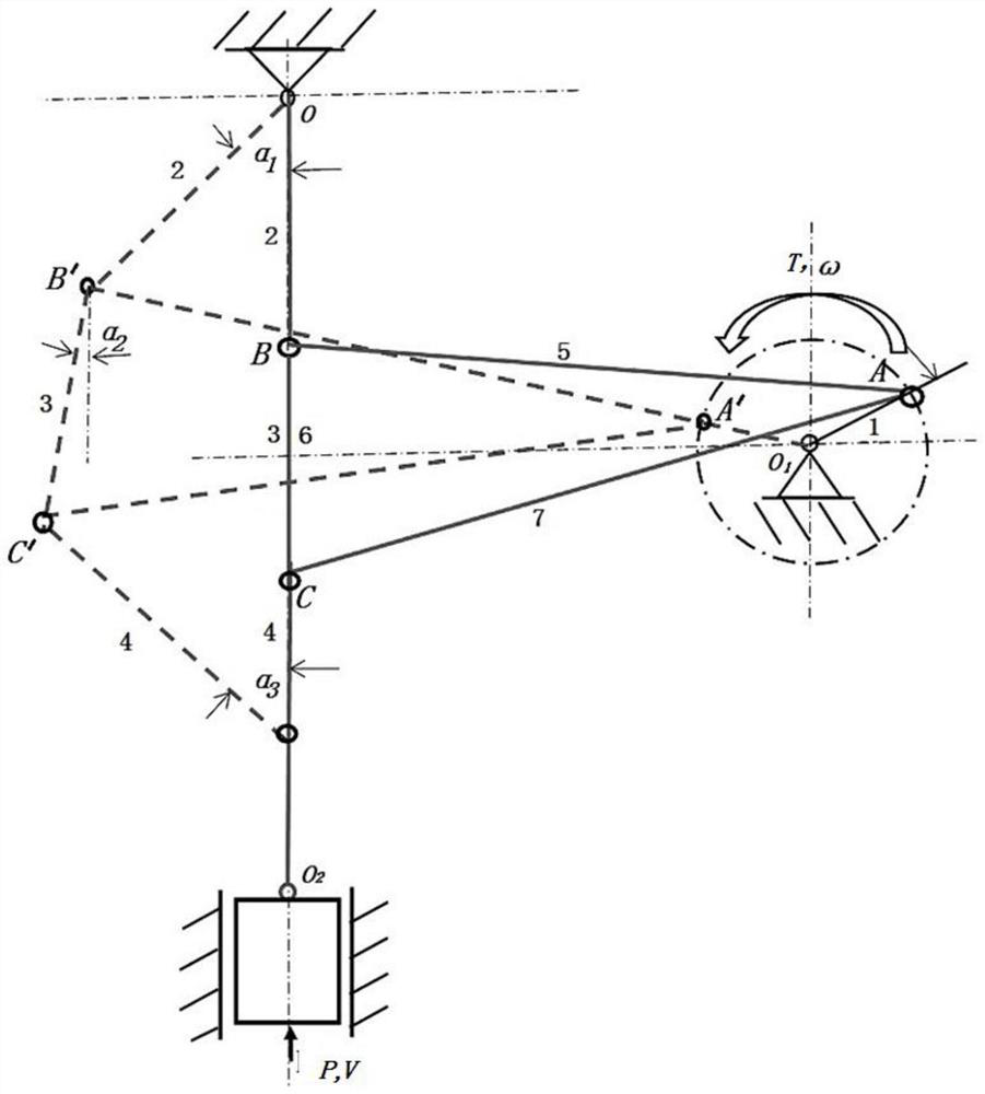
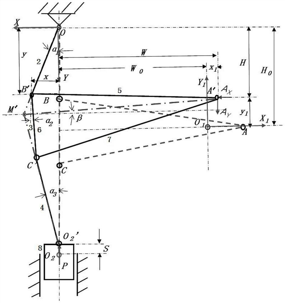
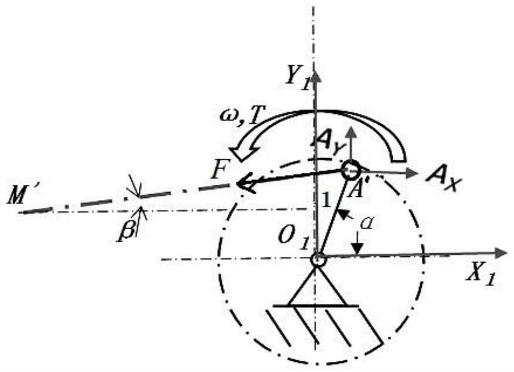
[0048] like Figure 1 to Figure 6 Shown is the staggered peak design method of the crank-triangular linkage-toggle linkage mechanism of the present invention, the crank-triangular linkage-toggle linkage includes sequentially articulated crank 1, triangular linkage ΔABC and toggle, and the toggle includes sequential The first toggle 2, the second toggle 3 and the third toggle 4 which are hingedly arranged, the triangular connecting rod comprises the first connecting rod 5, the second connecting rod 6 and the third connecting rod 7 which are sequentially hinged, and the triangular connecting rod The apex of the bar is hinged with the crank 1, the second connecting rod 6 of the bottom edge of the triangular connecting rod is integrated with the second toggle lever 3, and one end of the third toggle lever 4 is connected with a slide block 8. In this embodiment, the center of rotation of the crank is O 1 , the connection between the crank 1 and the triangular connecting rod is pro...

Embodiment 2

[0081] In practical applications, the combination of the crank mechanism and the triangular linkage-toggle mechanism can be in three different ways: upright (Scheme A), positive bias (Scheme B) and negative bias (Scheme C), such as Figure 7 to Figure 9 Shown; In order to simplify the calculation process of the present invention, the triangular connecting rod of this embodiment is set as an isosceles triangular connecting rod.

[0082] like Figure 7 Shown is a schematic diagram of the structure of the crank-triangular linkage-toggle mechanism upright, that is, when the slider is at the bottom dead center, the rotation center O of the crank 1 1 High AA on the bottom edge of the delta linkage 0 superior. At this time, AA 0 On the horizontal line, the first toggle 2, the second toggle 3 and the third toggle 4 are on the same vertical line, crank R and AA 0 co-existing horizontally. The maximum mechanical benefit A of the equivalent linear link-toggle linkage set up in this ...


PUM


Abstract

The present invention relates to the technical field of mechanical transmission, and more specifically, relates to a peak-staggered design method of a crank-triangular linkage-toggle linkage. Decompose the mechanism first, and decompose it into two sub-mechanisms: the crank-triangular linkage mechanism and the triangular linkage-toggle linkage mechanism; then analyze the motion and force of the two sub-organizations respectively, and obtain the expression of their respective maximum mechanical benefits Formula A 1max and A 2max ; By negatively biasing the mechanism, A 1max before A 2max appear, stagger a certain angle on the corresponding crank angle coordinates, and complete the preliminary design of the crank-triangular linkage-toggle linkage mechanism, which provides the basis for further computer simulation analysis and optimization. The present invention obtains great mechanical benefits in a large range of working strokes, and at the same time improves the kinematic characteristics of the sliders: reduces the average speed of the sliders in the working stroke and improves the stability of the speed, and has the advantages of reducing the capacity of the drive motor and improving the working performance of the sliders. Significance.

Description

technical field [0001] The present invention relates to the technical field of mechanical transmission, and more specifically, relates to a peak-staggered design method of a crank-triangular link-toggle link mechanism. Background technique [0002] The servo mechanical press is a new type of forging equipment that has appeared in recent years. It removes the flywheel, clutch, and brake, which not only simplifies the transmission chain, reduces energy consumption, and improves reliability, but also makes the motion characteristics of the slider change from uncontrollable to It improves the controllability and improves the automation and intelligence level of the equipment. In order to reduce the capacity of the drive motor, higher requirements are put forward for the working mechanism of the servo mechanical press: 1) The working stroke has as large a mechanical advantage as possible; 2) The working stroke has a low and uniform speed; 3) The idle stroke has High speed; 4) Th...

Claims


Application Information

Patent Timeline
Patent Type & Authority Patents(China)
IPC IPC(8): F16H21/26B21J9/18
CPCB21J9/18F16H21/26
Inventor 孙友松胡建国程永奇魏良模章争荣
Owner GUANGDONG UNIV OF TECH
Learn More