Laser Welding Method for Repairing Surface or Internal Defects of Base Metal

An internal defect, laser welding technology, used in laser welding equipment, welding equipment, workpiece edge parts, etc., can solve the problems of product scrap, loss, cracking, etc., to prevent undercut, prevent undercut defects, and ensure the overall structure of the equipment Effect

Active Publication Date: 2021-06-22
丁二纲
View PDF0 Cites 0 Cited by
  • Summary
  • Abstract
  • Description
  • Claims
  • Application Information

AI Technical Summary

Problems solved by technology

[0002] In the field of military industry and aerospace technology, it is generally made of precision special materials, which have extremely high requirements for the performance of the product. When there is a defect on the surface or inside of the product, it needs to be repaired by welding, otherwise the entire product will be scrapped, resulting in huge losses.
When laser welding repairs this type of defect, traditional welding methods generally use argon arc welding, cold welding, laser cladding, etc., and laser cladding is used to start welding from the bottom of the defect. When the laser beam irradiates the welding wire, only When the upper surface of the welding wire is irradiated, the lower surface of the welding wire will block the laser light, resulting in unfused phenomenon in the part covered by the welding wire, so that the repaired part and the base metal are not tightly bonded, forming a fragile area, and the repaired part still has undercuts , porosity, cracks and other defects are prone to cracking in actual use, affecting the overall performance of the equipment

Method used


Image

  • Laser Welding Method for Repairing Surface or Internal Defects of Base Metal
  • Laser Welding Method for Repairing Surface or Internal Defects of Base Metal
  • Laser Welding Method for Repairing Surface or Internal Defects of Base Metal

Examples


Embodiment Construction

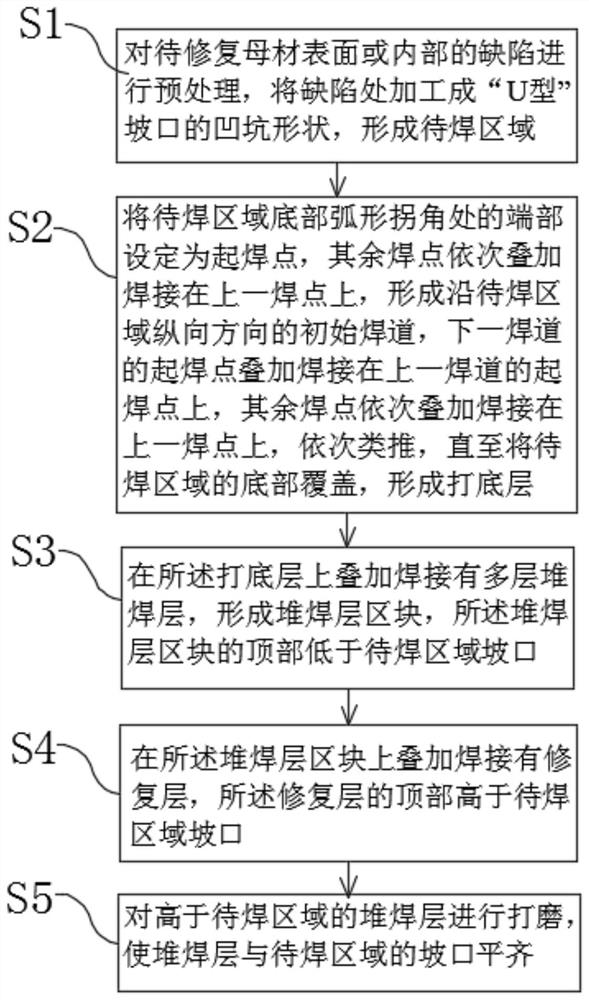
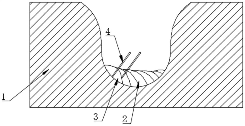
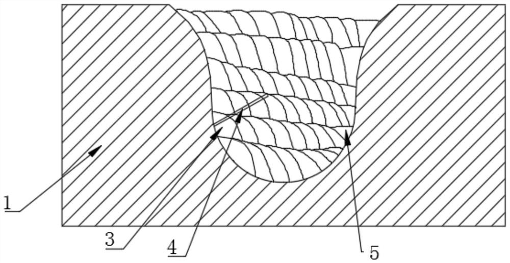
[0032] Such as Figure 1-Figure 6 As shown, a laser welding method for repairing base metal surface or internal defects of the present invention comprises the following steps:

[0033] S1. Pre-treat the defects on the surface or inside of the base metal to be repaired, and process the defects into the shape of a "U-shaped" groove pit to form the area to be welded.

[0034] Among them, prior to the pretreatment, the base metal is subjected to fluorescence detection and X-ray detection in sequence to determine the type of defect and the location of the defect, that is, to determine the type of defect as a defect on the surface or inside of the base metal, and the location of the defect in the base metal. Location.

[0035] Pretreatment is machining by machining center or manual processing by electric drill or grinding head. For the defects on the surface of the base metal, it is enough to directly process the defects into the pit shape of the "U-shaped" groove. For the defects ...


PUM

PropertyMeasurementUnit
diameteraaaaaaaaaa

Abstract

The invention relates to a laser welding method for repairing surface or internal defects of a base metal, comprising the following steps: S1, performing pretreatment on the surface or internal defects of the base metal to be repaired to form an area to be welded; S2, forming an arc at the bottom of the area to be welded The end of the corner is set as the starting point of welding, and the remaining welding points are superimposed and welded on the previous welding point in turn to form an initial welding bead along the longitudinal direction of the area to be welded, and the starting welding point of the next welding pass is superimposed and welded on the previous welding point. On the start welding point of the weld bead, the rest of the welding points are superimposed and welded on the previous welding point in turn, and so on, until the bottom of the area to be welded is covered to form a bottom layer; S3, multi-layer surfacing welding is superimposed on the bottom layer layer, forming a surfacing layer block, the top of the surfacing layer block is lower than the groove of the area to be welded; S4, a repair layer is superimposed on the surfacing layer block, and the top of the repair layer is higher than the groove of the area to be welded ; S5. Grinding the surfacing layer higher than the area to be welded, so that the surfacing layer is flush with the groove of the area to be welded.

Description

technical field [0001] The invention relates to the technical field of repairing precision special material products, in particular to a laser welding method for repairing surface or internal defects of a parent material. Background technique [0002] In the field of military industry and aerospace technology, it is generally made of precision special materials, which have extremely high requirements for the performance of the product. When there is a defect on the surface or inside of the product, it needs to be repaired by welding, otherwise the entire product will be scrapped, resulting in huge losses. . When laser welding repairs this type of defect, traditional welding methods generally use argon arc welding, cold welding, laser cladding, etc., and laser cladding is used to start welding from the bottom of the defect. When the laser beam irradiates the welding wire, only When the upper surface of the welding wire is irradiated, the lower surface of the welding wire wil...

Claims


Application Information

Patent Timeline
Patent Type & Authority Patents(China)
IPC IPC(8): B23K26/342B23K26/60B23K33/00
CPCB23K33/00B23K26/342B23K26/60
Inventor 丁二纲王素敏王宾石明星李勇
Owner 丁二纲
Why Eureka
Try Eureka