Downer reactor and catalytic conversion method

A catalytic conversion and reactor technology, which is applied in chemical instruments and methods, catalytic cracking, cracking, etc., can solve the problems of short contact time of agent oil and insufficient reaction, and achieve short contact time of agent oil, good gasoline quality, and transformation low cost effect

Active Publication Date: 2019-04-23
CHINA PETROLEUM & CHEM CORP +1
View PDF23 Cites 2 Cited by
  • Summary
  • Abstract
  • Description
  • Claims
  • Application Information

AI Technical Summary

Problems solved by technology

[0007] It can be found from the above-mentioned patents that when the down-flow reactor is used, back-mixing can be avoided to a large extent, and some undesirable side reactions can be reduced. There is still room for further improvement

Method used


Image

  • Downer reactor and catalytic conversion method
  • Downer reactor and catalytic conversion method
  • Downer reactor and catalytic conversion method

Examples


Embodiment approach

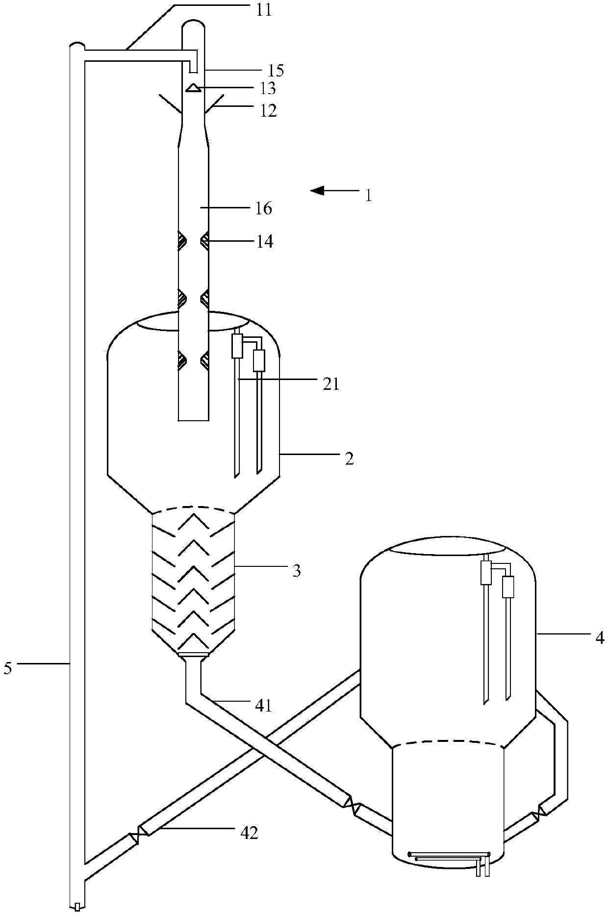
[0049] One embodiment, the top surface of the catalyst distributor 13 is a conical surface, so that the catalyst forms a uniformly dispersed annular curtain, for example, it can be a conical baffle with the tip of the cone facing upwards, and the conical baffle can be connected with the agent. The oil contact section 15 is coaxial and forms an annulus for the passage of the catalyst with the agent oil contact section 15 . The ratio of the bottom outer diameter of the catalyst distributor 13 to the agent oil contact section 15 inner diameter can be 1: (1.1-4), and the ratio of the bottom outer diameter of the catalyst distributor 13 to the height of the catalyst distributor 13 can be 1: (0.1-5).

[0050] An implementation, such as figure 1 As shown, the down-flow reactor 1 is also provided with a catalyst inlet line 11, and the catalyst inlet line 11 extends from the catalyst inlet of the agent-oil contact section 15 into the agent-oil contact section 15 and makes the catalyst...

Embodiment 1

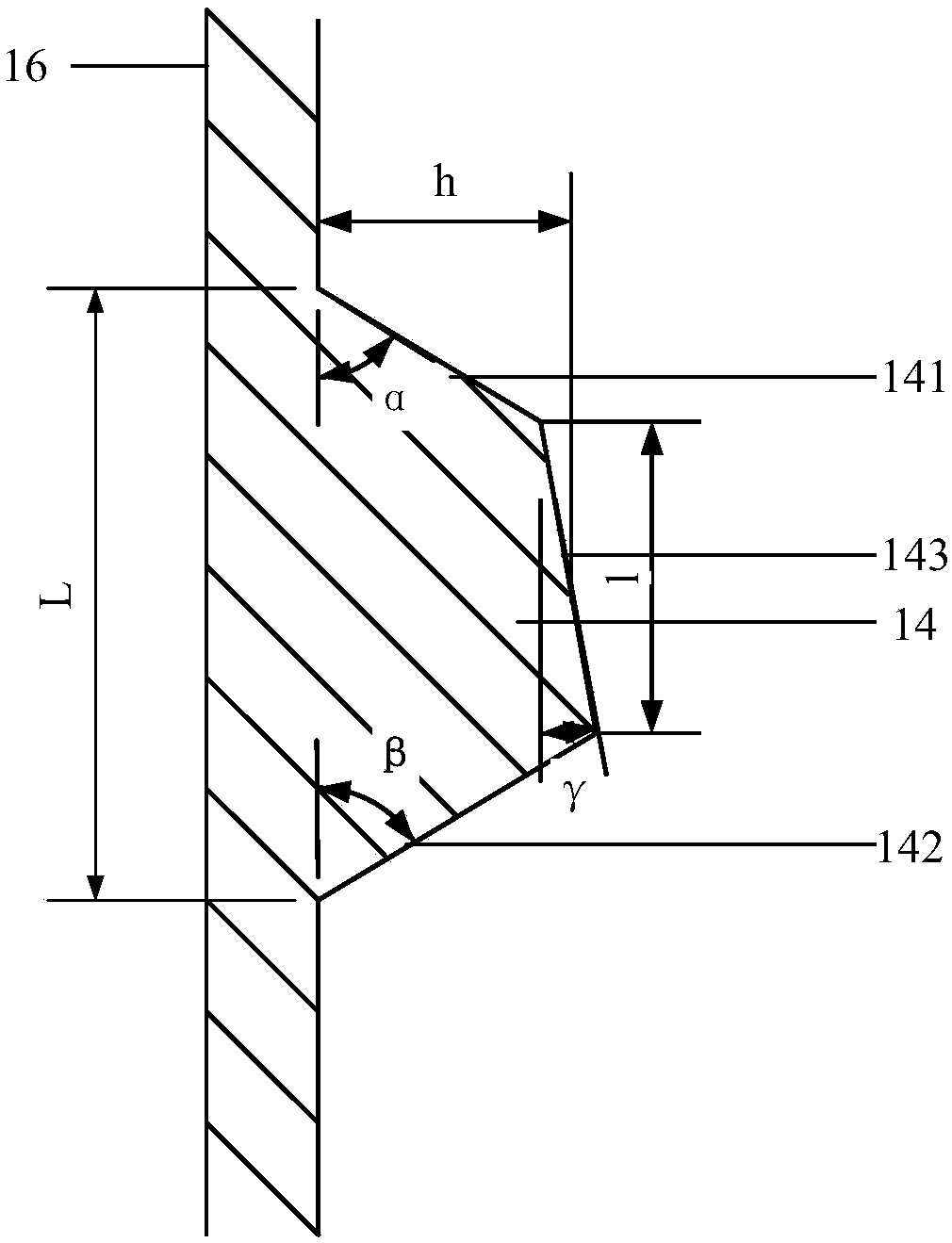
[0068] The embodiment of the present invention is to carry out on medium-scale test device, and its flow process is as follows figure 1 As shown, there is one catalyst distributor and three annular baffles in the down-flow reactor, and the main reaction section is equal in diameter. Ring baffle structure such as figure 2 As shown, α is 50°, β is 60°, γ is 15°, distance h is 0.15 of the inner diameter length of the main reaction section, the ratio of length l to distance h is 1, length l is 0.4 of length L, and an annular stop is set The length of the main reaction section of the plate accounts for 1 / 2 of the total length of the main reaction section 16, and the distance between adjacent annular baffles is equal. The catalyst distributor is a conical baffle, the ratio of the bottom outer diameter of the conical baffle to the inner diameter of the agent-oil contact section is 1:1.67, the ratio of the bottom outer diameter of the conical baffle to its height is 1:3, and the cat...

Embodiment 2

[0071] The reaction flow process of embodiment 2 is identical with embodiment 1, and the baffle plate shape parameter is identical with embodiment 1, difference is that the number of described annular baffle 13 is 5, the length of the main reaction section of setting annular baffle Accounting for 3 / 4 of the total length of the main reaction section 16, the annular baffles are arranged at equal intervals from top to bottom. The specific reaction conditions and reaction results are shown in Table 2.


PUM


Abstract

The present invention relates to a downer reactor and a catalytic conversion method. The downer reactor (1) sequentially comprises an agent-oil contact section (15) and a main reaction section (16) from top to bottom, wherein the agent-oil contact section (15) and the main reaction section (16) are coaxially arranged and are fluidly communicated, the agent-oil contact section (15) is sequentiallyprovided with a catalyst inlet and a raw material oil spraying nozzle (12) from top to bottom, and the inner wall of the main reaction section (16) is provided with at least an annular baffle (14) coaxial with the main reaction section (16). The catalytic conversion method using the downer reactor of the present invention has high low-carbon olefin yield.

Description

technical field [0001] The invention relates to a descending reactor and a catalytic conversion method. Background technique [0002] Low carbon olefins (C 2 -C 4 Alkenes) are important chemical raw materials. At present, the leading technology for producing ethylene and propylene worldwide is steam cracking, and more than 95% of ethylene and 60% of propylene are obtained through this technology. From a global perspective, 48% of cracking raw materials are naphtha, 33% of ethane, 8% of propane, about 5% of butane, 4% of oil and gas, and about 2% of others. In the process of steam cracking, since there is no catalyst, the cracking of hydrocarbons requires relatively harsh operating conditions, which makes the cost of production and equipment construction relatively high, and crude oil is becoming increasingly heavy, and the shortage of light hydrocarbon raw materials is becoming more and more serious. The technical route of producing low-carbon olefins from raw materials ...

Claims


Application Information

Patent Timeline
Patent Type & Authority Applications(China)
IPC IPC(8): C10G11/18B01J8/18
CPCB01J8/003B01J8/1881B01J2208/00884C10G11/182C10G2300/703C10G2400/20
Inventor 成晓洁朱根权谢朝钢
Owner CHINA PETROLEUM & CHEM CORP
Why Eureka
Try Eureka