
Micro-liquidity composite polishing die for large-caliber easily deformed zinc sulfide optical window parts and manufacturing method thereof

An optical window and composite polishing technology, which is applied in the direction of grinding/polishing equipment, manufacturing tools, grinding machine parts, etc., can solve the problems of uneven surface shape accuracy, long processing cycle, and easy deformation of multi-spectral zinc sulfide optical windows. Difficult polishing processing and other problems, to achieve the effect of regular motion trajectory, controllable motion trajectory, and solve the problem of shrinking heat conduction groove and plugging

Active Publication Date: 2019-04-26
西安应用光学研究所
View PDF5 Cites 1 Cited by
  • Summary
  • Abstract
  • Description
  • Claims
  • Application Information

AI Technical Summary

Problems solved by technology

Among them, the effect of magnetorheological ultra-smooth polishing mainly depends on the processing accuracy of magnetorheological polishing equipment, but currently there is no magnetorheological ultra-smooth polishing equipment that can be used for polishing large-diameter and deformable multi-spectral zinc sulfide optical windows above 600mm; However, the traditional (classical) large-scale asphalt grinding and polishing method has problems such as long processing cycle for large-caliber optical parts (for 600mm-caliber optical parts, the entire process processing cycle is not less than half a year), uneven surface shape accuracy, etc., resulting in large-diameter parts above 600mm Difficult Polishing of Deformable Multispectral ZnS Optical Window

Method used


Image

  • Micro-liquidity composite polishing die for large-caliber easily deformed zinc sulfide optical window parts and manufacturing method thereof
  • Micro-liquidity composite polishing die for large-caliber easily deformed zinc sulfide optical window parts and manufacturing method thereof

Examples


Embodiment Construction

[0037] Embodiments of the present invention are described in detail below, and the embodiments are exemplary and intended to explain the present invention, but should not be construed as limiting the present invention.

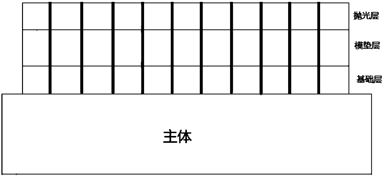
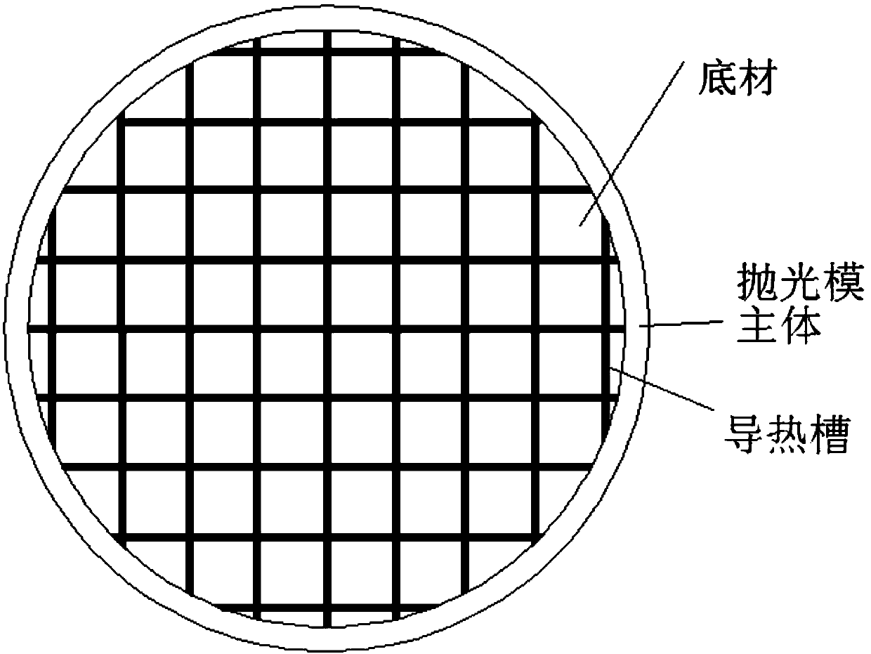
[0038] Such as figure 1 As shown, a microfluidic composite polishing mold for large-diameter deformable zinc sulfide optical window parts above 600mm in this embodiment consists of a polishing mold main body, a base layer, a mold cushion layer and a polishing layer.

[0039] The expansion coefficient of the main body material of the polishing mold is 1.2×10⁻⁵ / ℃~0.8×10⁻⁶ / ℃, the modulus of elasticity is 120GPa~40GPa; the flatness of the working surface of the main body of the polishing mold is 0.2μm~8μm, and the surface roughness is 0.012μm~1μm; the cross-sectional shape of the main body of the polishing die is circular, the diameter-to-thickness ratio is 8:1-10:1, and the diameter is larger than the diameter or diagonal size of the large-diameter deformable zin...


PUM

PropertyMeasurementUnit
elastic modulusaaaaaaaaaa
softening pointaaaaaaaaaa
thicknessaaaaaaaaaa

Abstract

The invention provides a micro-liquidity composite polishing die for large-caliber easily deformed zinc sulfide optical window parts and a manufacturing method of the micro-liquidity composite polishing mold. The polishing die comprises a polishing die body, a base layer, a die cushion layer and a polishing layer. A low-expansion high-stability material is adopted as the polishing die body, optical asphalt and a die cushion are combined to serve as a base material, and the novel polishing die is formed by hot pressing molding of a standard plane pressing plate, so that the optical asphalt andthe die cushion are tightly combined. Micro holes are formed in the die cushion material, and the die cushion is soaked in the optical asphalt, so that the die cushion is tightly combined with the upper layer of optical asphalt and the lower layer of optical asphalt, the flow of the upper-layer optical asphalt and the flow of the lower-layer optical asphalt are stably controlled, and the defect that the upper-layer optical asphalt and the lower-layer optical asphalt flow easily is overcome.

Description

technical field [0001] The invention belongs to the technical field of cold processing of optical parts, in particular to a microfluidity composite polishing mold for large-caliber easily deformable zinc sulfide optical window parts and a manufacturing method thereof. Background technique [0002] The polishing principle of optical glass adopts the principle of mechanical grinding, which is the result of tiny cutting action on the glass surface based on sharp and hard abrasive particles. Traditional (classical) polishing dies usually consist of a body (usually aluminum alloy or steel) and a substrate (such as sanding pads, asphalt, fabric or felt). For large-caliber deformable multi-spectral zinc sulfide optical window optical parts above 600mm, since the zinc sulfide optical material itself is a brittle material with a soft surface and poor wear resistance, and the ratio of window glass diameter to thickness is too large, the overall Factors such as heavy weight and high s...

Claims


Application Information

Patent Timeline
Patent Type & Authority Applications(China)
IPC IPC(8): B24B1/00B24B41/00
CPCB24B1/00B24B41/00
Inventor 冯耕李明伟吴斌王松林郑军刚马方斌张岩韩娟妮
Owner 西安应用光学研究所
Learn More