Oil and water separation and purification system for automobile coating wastewater

A coating wastewater and oil-water separation technology, which is applied in the field of wastewater treatment and environmental protection equipment, can solve the problems of small processing capacity, high cost of filtration membrane, unsatisfactory effect, etc., and achieve the effect of improved purification rate and refined oil-water separation

Active Publication Date: 2019-04-26
中汽(天津)系统工程有限公司
View PDF6 Cites 2 Cited by
  • Summary
  • Abstract
  • Description
  • Claims
  • Application Information

AI Technical Summary

Problems solved by technology

Chinese Patent Authorized Announcement No. CN101072616A relates to an oil-water separation device. The container is divided into several grooves, which are naturally separated by density, and the effect is not ideal; Chinese Patent Authorized Announcement No. CN202279752U relates to an oil-water separation and purification device for automobile painting wastewater. After the CUF oil-water separator is connected with the pre-degreasing tank and the degreasing tank, the circulating water is separated from oil and water, but the effect of oil-water separation depends on the CUF oil-water separator, and the cost of the filter membrane is high, and the processing capacity is small, so it is not suitable for large-scale applications. Production enterprises with a large amount of sewage

Method used


Image

  • Oil and water separation and purification system for automobile coating wastewater
  • Oil and water separation and purification system for automobile coating wastewater
  • Oil and water separation and purification system for automobile coating wastewater

Examples


Embodiment Construction

[0035] The technical solutions of the present invention will be clearly and completely described below in conjunction with the accompanying drawings. Apparently, the described embodiments are some of the embodiments of the present invention, but not all of them. Based on the embodiments of the present invention, all other embodiments obtained by persons of ordinary skill in the art without making creative efforts belong to the protection scope of the present invention.

[0036] In the description of the present invention, it should be noted that the terms "center", "upper", "lower", "left", "right", "vertical", "horizontal", "inner", "outer" etc. The indicated orientation or positional relationship is based on the orientation or positional relationship shown in the drawings, and is only for the convenience of describing the present invention and simplifying the description, rather than indicating or implying that the referred device or element must have a specific orientation, ...


PUM


Abstract

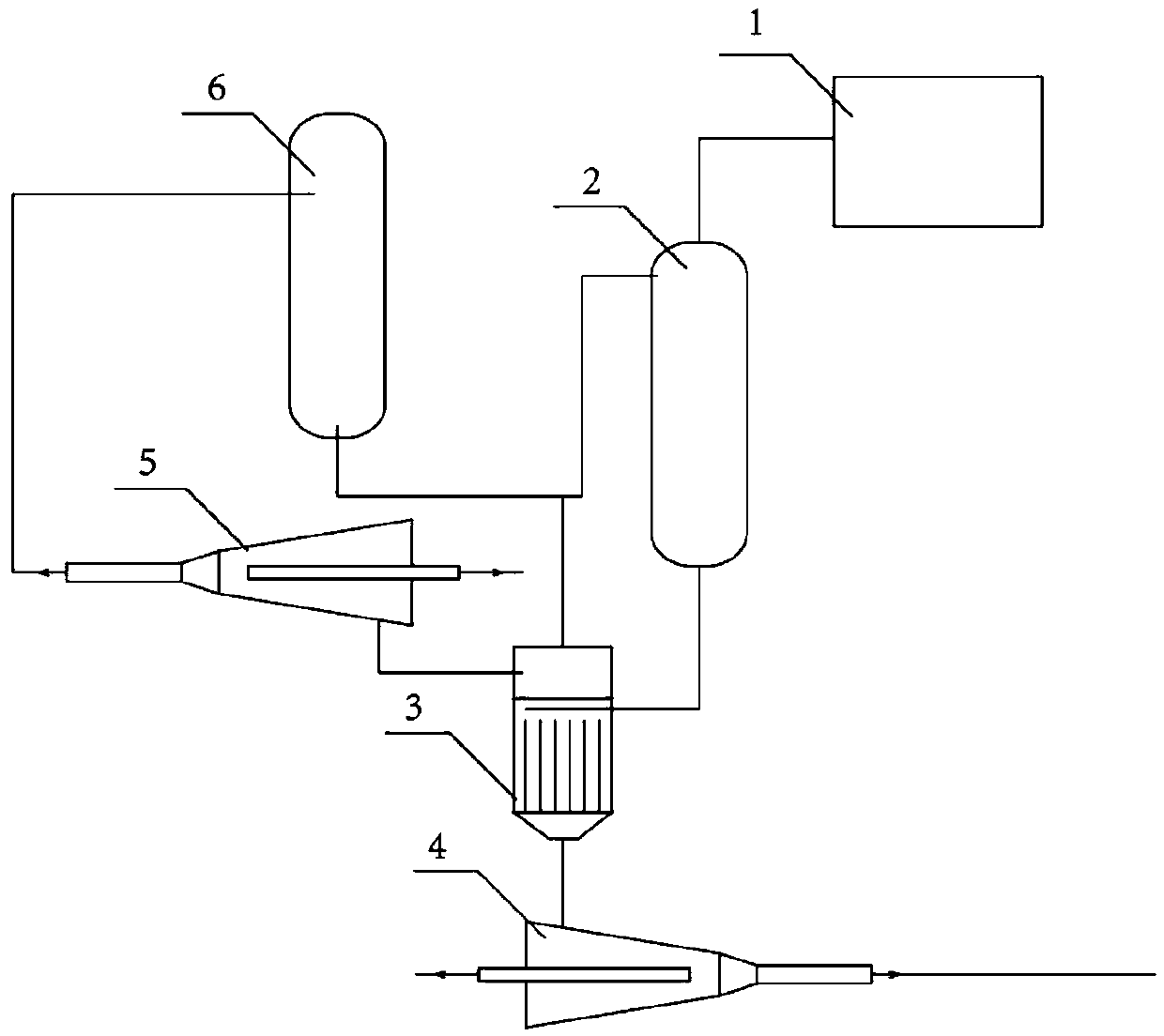
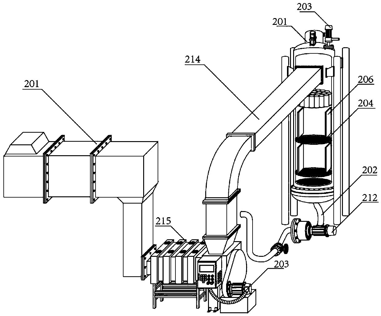
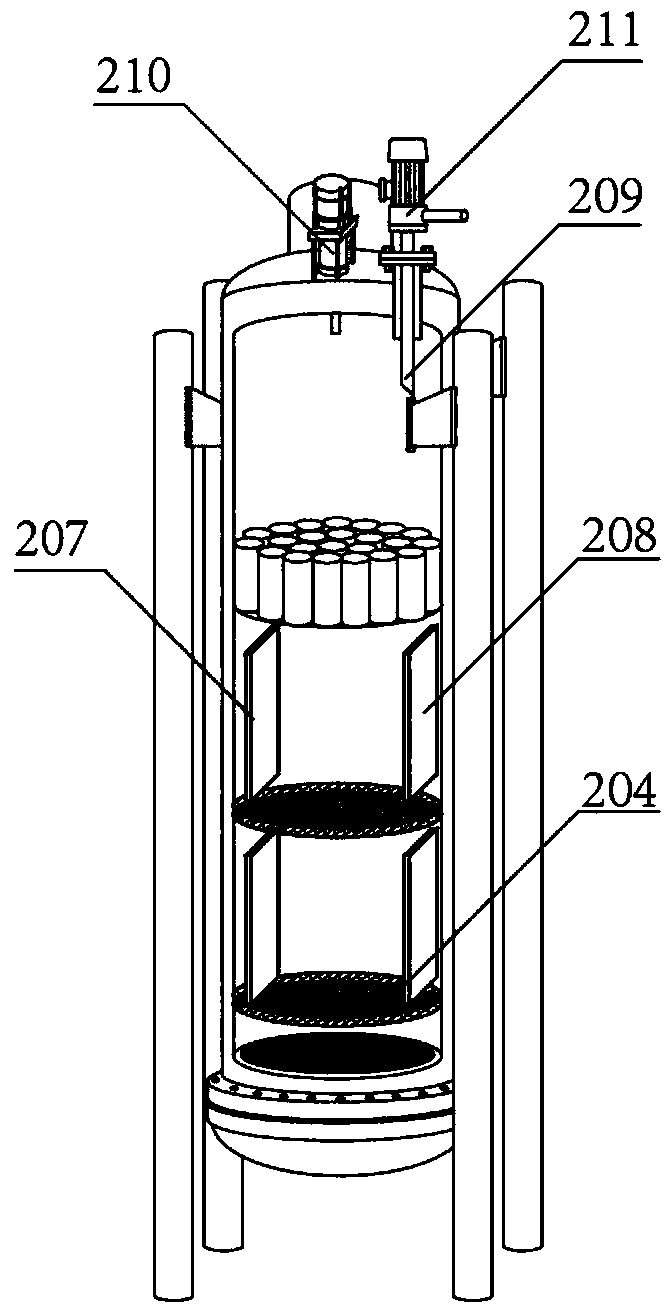
The invention relates to an oil and water separation and purification system for automobile coating wastewater. The oil and water separation and purification system for the automobile coating wastewater comprises a wastewater collecting system, a crude separation system, a water separation type whirlcone, an oil separation type whirlcone as well as pipelines for connection, and is characterized inthat the crude separation system comprises a multi-stage filtering tower and a low-boiling-point evaporation device; coating wastewater is collected and differentiated by the wastewater collecting system, enters the multi-stage filtering tower to be filtered and enters the low-boiling-point evaporation device; high-boiling-point wastewater which flows out of the low-boiling-point evaporation device enters the water separation type whirlcone; low-boiling-point wastewater enters the oil separation type whirlcone; the multi-stage filtering tower and the low-boiling-point evaporation device communicate with a tail gas purification device; and spraying water of the tail gas purification device is connected with a water phase outlet of the oil separation type whirlcone. The wastewater is divided into two ways to be treated separately and the treatment quantity is large, so that the wastewater treatment efficiency is improved and the oil and water separation effect is improved; furthermore,waste water in the wastewater treatment process is purified, so that unpleasant odor or toxic and pungent odor generated in the wastewater treatment process is treated.

Description

technical field [0001] The invention relates to the field of waste water treatment, in particular to a system for treating waste water from automobile painting, in particular to a system for purifying oil and water in waste water from automobile painting, which belongs to the field of environmental protection equipment. Background technique [0002] The wastewater produced in the production process of automobile painting mainly comes from the production processes such as body-in-white surface treatment, electrophoresis and paint spraying. During the surface treatment process, it is necessary to wash to remove the anti-rust oil on the body surface. After electrophoresis, it is necessary to rinse off the remaining electrophoretic paint on the body surface. In the spraying process, it is necessary to use circulating water to capture the sprayed paint mist. The above flushing wastewater and circulating wastewater contain resins, surfactants, heavy metal ions, oil, PO 3 4- , pai...

Claims


Application Information

Patent Timeline
Patent Type & Authority Applications(China)
IPC IPC(8): C02F9/12
CPCC02F9/00C02F1/48C02F1/66C02F1/001C02F1/04C02F1/40Y02W10/37
Inventor 李伟战尹忠岩
Owner 中汽(天津)系统工程有限公司
Why Eureka
Try Eureka