
Steam condensing and recovering system

A steam system and condensation recovery technology, which is applied in steam/steam condensers, refrigerators, refrigeration and liquefaction, etc., can solve the problems of high steam humidity, poor use experience, energy waste, etc., and achieve zero emission and condensation Effect

Pending Publication Date: 2019-04-26
太仓瑞普精密机械有限公司
View PDF0 Cites 10 Cited by
  • Summary
  • Abstract
  • Description
  • Claims
  • Application Information

AI Technical Summary

Problems solved by technology

[0004] However, the above air exhaust device has the following defects: 1. Due to factors such as limited condensation space, shell material, cooling medium, cooling area, etc., the condensing return chamber cannot completely condense and recycle the steam, resulting in energy waste; 2. The humidity of the discharged steam is high. , mixed with food smell and grease, seriously causing environmental pollution and humidity in the kitchen; 3. During the discharge process of the air duct of the body, it is easy to encounter the cold state of the environment to form condensed water and remain inside the air duct of the body, the air outlet, and the inner panel of the sliding door , affecting the performance and life of the machine; 4. The temperature of the discharged steam is relatively high, which is easy to cause burns and the use experience is poor

Method used


Image

  • Steam condensing and recovering system
  • Steam condensing and recovering system
  • Steam condensing and recovering system

Examples


no. 1 example

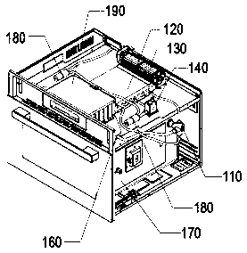
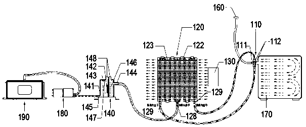
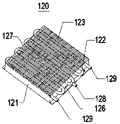
[0039] Please refer to figure 1 and figure 2 , figure 1Show the use state diagram of the condensate recovery steam system, figure 2 Schematic showing the condensate recovery vapor system. The condensing steam recovery system includes a switching orienter 110 , a condensing device 120 , a cold power source 130 and a purified and filtered water storage tank 140 . The switching orienter 110 has a three-way port and is installed in the cooking inner cavity 170. The one-way port 111 is connected to the ventilation interface seat 160, and the two-way port 112 is connected to the condensing device 120 for condensing saturated waste steam. The purified and filtered water storage tank 140 is also connected to the condensing device 120 . The cold power source 130 is used to provide cold air to the condensing device 120 . It should be noted that the switching orienter 110 has or can be two-way ports or other number of ports more than two-way. As long as there are ports connected t...

no. 2 example

[0047] Please refer to Figure 8-Figure 12 , the present embodiment provides a condensing recovery steam system, which is substantially the same as the condensing recovery steam system in the first embodiment, the difference between the two lies in the structure of the condensing device 120 in this embodiment.

[0048] Please continue to refer to Figure 8-Figure 10 , the condensation device 120 includes a refrigerator generating source 221 , a heat conducting plate 222 , an NP type semiconductor cold chip 223 , a cold conducting plate 224 , a condensation box 225 and a silicone sealing ring 226 . The refrigerator generating source 221 , heat conduction fins 222 , NP type semiconductor cold chips 223 , and cold conduction fins 224 are arranged sequentially from top to bottom. In this embodiment, the refrigerator generating source 221 is an axial flow cooling fan, please refer to Figure 11 , is a schematic diagram of the installation of the condensing device 120 in this embo...


PUM


Abstract

The invention provides a steam condensing and recovering system, and relates to the technical field of steam condensing of kitchen appliances. The system comprises a switching direction finger which is mounted in an inner cooking chamber body and is provided with a T-shaped port, a condensing device for condensing saturated wasted steam, a cold power source which is arranged on the condensing device and is used for supplying cold air to the condensing device, and a purifying filtering water storing tank which is connected to the condensing device, wherein the condensing device is provided withtwo hot steam inlets and a condensed water outlet; after flowing out through the condensed water outlet, condensed water sequentially flows through the purifying filtering water storing tank and a water returning pump and then is returned to a water tank; the hot steam inlet is connected to a two-way port of the switching direction finder through a pipeline; and an one-way port of the switching direction finder is connected to a ventilating joint seat. According to the system, the saturated wasted steam is condensed through the condensing device, so that the steam condensing and zero emissionare effectively realized; the smell of foods can be removed through the purifying filtering water storing tank, and clean condensed water can be collected.

Description

technical field [0001] The invention relates to the technical field of steam condensation of kitchen appliances, in particular to a system for condensing and recovering steam. Background technique [0002] At present, electric steamers, steam ovens, integrated steaming and baking machines, integrated steaming and micro steaming machines, and integrated micro-steaming and baking machines in kitchen appliances are mainly used for cooking and heating in the steaming mode. The inner cavity is a normal pressure structure without sealing pressure. The chamber is equipped with an external steam exhaust device, which is used to balance the pressure of the inner chamber and dynamically discharge the saturated waste steam that has been used in the inner chamber. [0003] During the working process of steam cooking, the inner cavity maintains normal pressure or slight pressure to avoid the danger of high pressure in the inner cavity. The fresh steam in the inner cavity is continuously ...

Claims


Application Information

Patent Timeline
IPC IPC(8): F28B1/06F28B9/00F28B9/02F28B9/08F28B11/00F25B21/02C02F1/00
CPCF25B21/02F28B1/06F28B9/00F28B9/02F28B9/08F28B11/00C02F1/001
Inventor 贾先锋
Owner 太仓瑞普精密机械有限公司
Learn More