A high-efficiency and energy-saving battery pack heater for new energy vehicles
A new energy vehicle, high-efficiency and energy-saving technology, applied in the field of new energy vehicle battery pack heaters, can solve the problems of large shell deformation, large space occupation, poor sealing effect, etc., achieve small structural design size, increase welding area, improve The effect of weld strength
- Summary
- Abstract
- Description
- Claims
- Application Information
AI Technical Summary
Problems solved by technology
Method used
Image
Examples
Embodiment 1
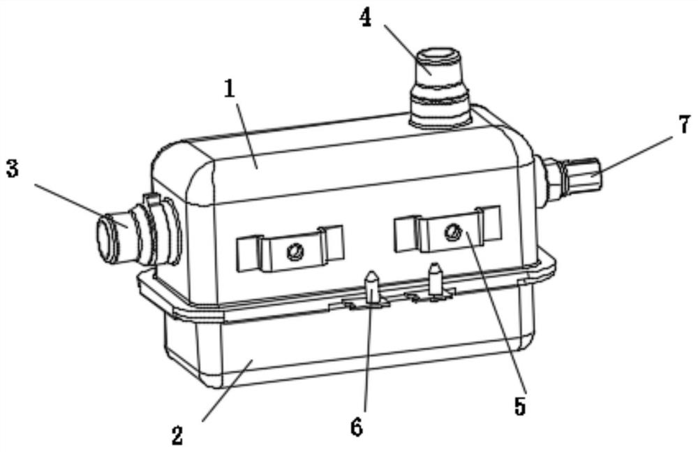
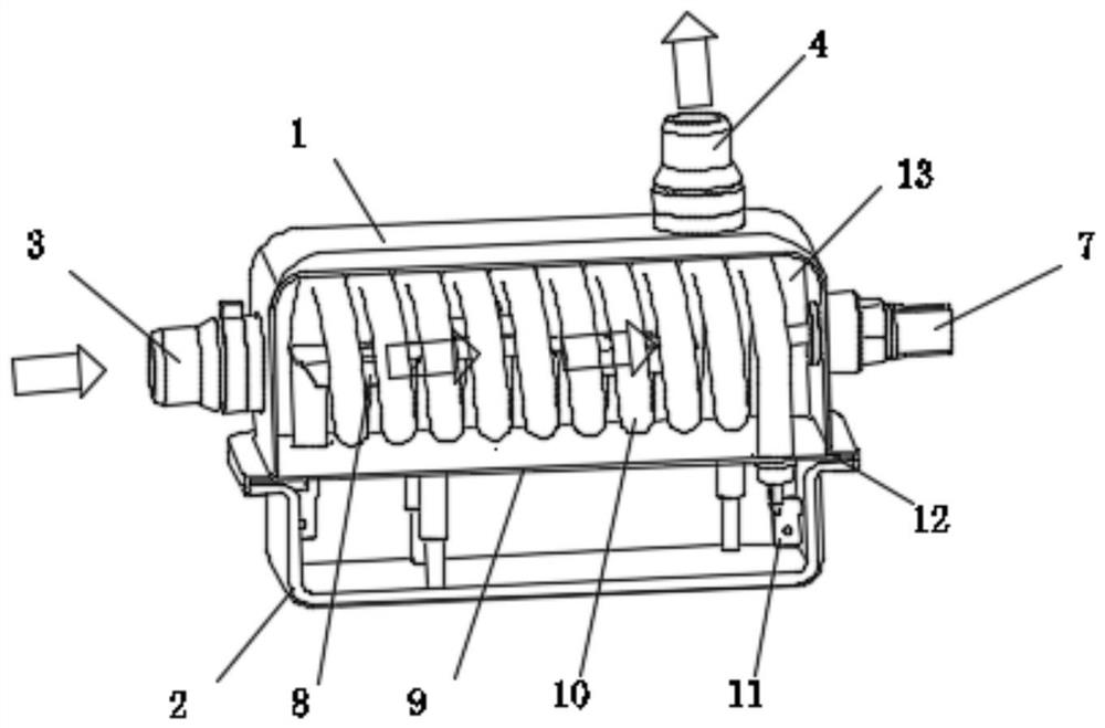
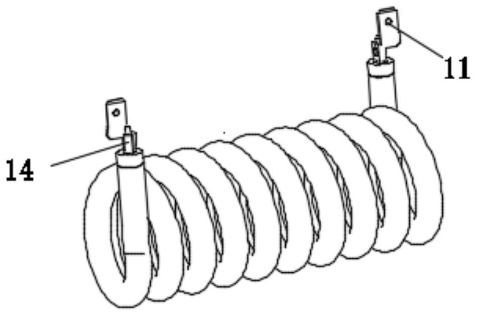
[0031] Embodiment 1: As shown in the figure, a high-efficiency and energy-saving new energy vehicle battery pack heater mainly includes an upper casing 1 and a lower casing 2, and the upper casing 1 is provided with an inlet pipe 3 and an outlet pipe 4. The inlet pipe 3 is arranged on the side of the upper casing 1 , and the outlet pipe 4 is arranged on the top surface of the upper casing 1 . A flange 9 is arranged between the upper shell 1 and the lower shell 2, and the upper shell 1 and the flange 9 form a heating chamber 13, and an electric heating tube 10 and a spoiler 8 are arranged in the heating chamber 13, and the liquid flows from the inlet pipe 3 flows through the heating chamber 13 and flows out from the outlet pipe 4, and the spoiler 8 forces the liquid flowing into the inner cavity of the electric heating tube 10 to flow to both sides ( figure 2 The middle arrow is the flow direction of the heating liquid); the spoiler 8 is set on the inner side of the electric h...
Embodiment approach
[0037] 1. After preparing the flange and forming the electric heating tube, put the electric heating tube into the flanging hole on the flange, then fix the nozzle by spot welding, and apply solder on the welding place;
[0038] 2. Prepare the spoiler;
[0039] 3. Squeeze the spoiler into the inner ring of the electric heating tube through deformation, and get stuck on the electric heating tube
[0040] 4. Prepare the inlet pipe, outlet pipe, temperature sensor joint, and fixed bracket, spot weld the fixed bracket, inlet pipe, outlet pipe, and temperature sensor joint according to the positions shown in the figure, and finally apply solder on the welding place;
[0041] 5. Prepare the annular welding sheet (thin sheet)
[0042] 6. The welding piece is transferred to the flange of the upper shell;
[0043] 7. Assemble the components in step 3 to the components in step 6, and then put them together in a high-temperature furnace for overall brazing
[0044] 8. Spot weld the we...
Embodiment 2
[0047] Embodiment 2: The difference with Embodiment 1 is: as Figure 11-Figure 12 The spoiler 8 is arranged in the heating chamber 13 close to the inlet pipe 3, and has a triangular bracket structure.
PUM
 Abstract
Description
Claims
Application Information
 - R&D
- Intellectual Property
- Life Sciences
- Materials
- Tech Scout
- Unparalleled Data Quality
- Higher Quality Content
- 60% Fewer Hallucinations
Browse by: Latest US Patents, China's latest patents, Technical Efficacy Thesaurus, Application Domain, Technology Topic, Popular Technical Reports.
© 2025 PatSnap. All rights reserved.Legal|Privacy policy|Modern Slavery Act Transparency Statement|Sitemap|About US| Contact US: help@patsnap.com


