Electroplating automatic line exhaust mechanism

An automatic line and fan technology, applied in the electrolysis process, electrolysis components, cells, etc., can solve the problems of not being able to ensure that all exhaust gas is sucked into the wind hood, polluting the workshop environment, and increasing the amount of exhaust gas, so as to save training costs, facilitate operation, and reduce The effect of active power

Pending Publication Date: 2019-05-03
万向新元绿柱石(天津)科技有限公司
View PDF0 Cites 2 Cited by
  • Summary
  • Abstract
  • Description
  • Claims
  • Application Information

AI Technical Summary

Problems solved by technology

[0006] The exhaust air of the two air hoods covers the space 0.3m above the liquid surface of the plating tank. Due to the large space, the air pressure loss cannot ensure that all the exhaust gas is sucked into the air hoods and pollutes the workshop environment. When the parts-hangers enter and exit the plating tank, the The solution will inevitably cause vertical agitation, and the amount of exhaust gas will increase. At the same time, the exhaust air will not change with the deterioration of the working conditions, causing more exhaust gas to escape into the working environment. The driving source of this structure operates according to the rated power, causing resource pollution. wasteful, high energy consumption

Method used


Image

  • Electroplating automatic line exhaust mechanism
  • Electroplating automatic line exhaust mechanism
  • Electroplating automatic line exhaust mechanism

Examples


Embodiment 1

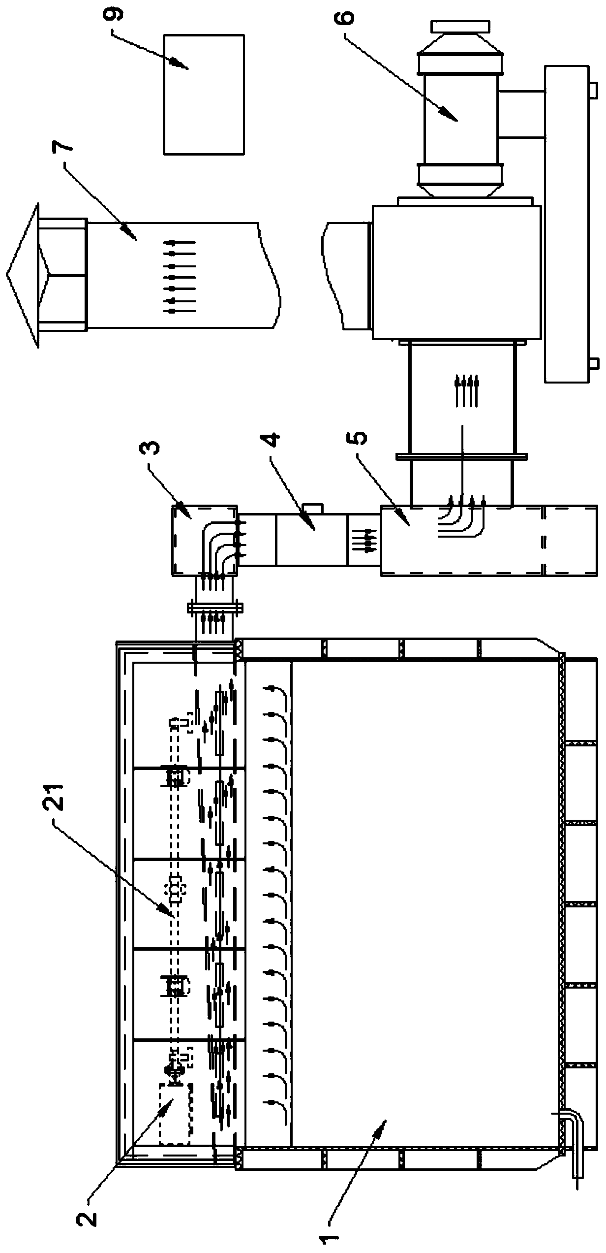
[0062] Embodiment 1: To compare the parameters of this structure and the conventional exhaust fan mechanism, the experimental conditions are set as follows.

[0063] 1. Surface area of ​​ventilation test tank: 1.5*0.8m

[0064] 2. Air cover 22 on both sides of the groove: traditional slit type air cover 22 and exhaust fan 6 of this structure

[0065] 3. Fan 6: exhaust air volume 2456m3 / h, wind pressure 1100Pa

[0066] 4. Chimney 7 outlet: the diameter is 315mm.

[0067] 5. Test bath: 75-85 degrees hot water

[0068] The following table is a comparison table of the suction parameters of the traditional slit-type windshield 22 and the exhaust fan 6 mechanism of the present structure.

[0069]

[0070] As can be seen from the table above, the traditional air cover 22 and fan 6 are in the high-speed operation state of 50HZ for a long time, and there is still a lot of steam and exhaust gas overflowing from the liquid surface of the solution tank 1, resulting in a humid workin...

Embodiment 2

[0071] Embodiment 2: The driving assembly 21 can be a driving cylinder and a connecting rod structure. On the premise that the space permits, it can directly drive the flap 24 to move through the driving cylinder to realize the rotation of the flap 24, and then realize the opening and closing of the flap 24 Action, if the space is limited, the drive cylinder can realize the action of the turnover plate 24 through the connection structure.

Embodiment 3

[0072] Embodiment 3: The driving assembly 21 can be a rack and pinion structure, and a gear is arranged coaxially on the turning shaft of the turning plate 24, and a rack is arranged to mesh with the gear, and the rack moves up and down under the action of the cylinder or the motor screw to drive the gear Rotate, realized the rotation of turning plate 24.

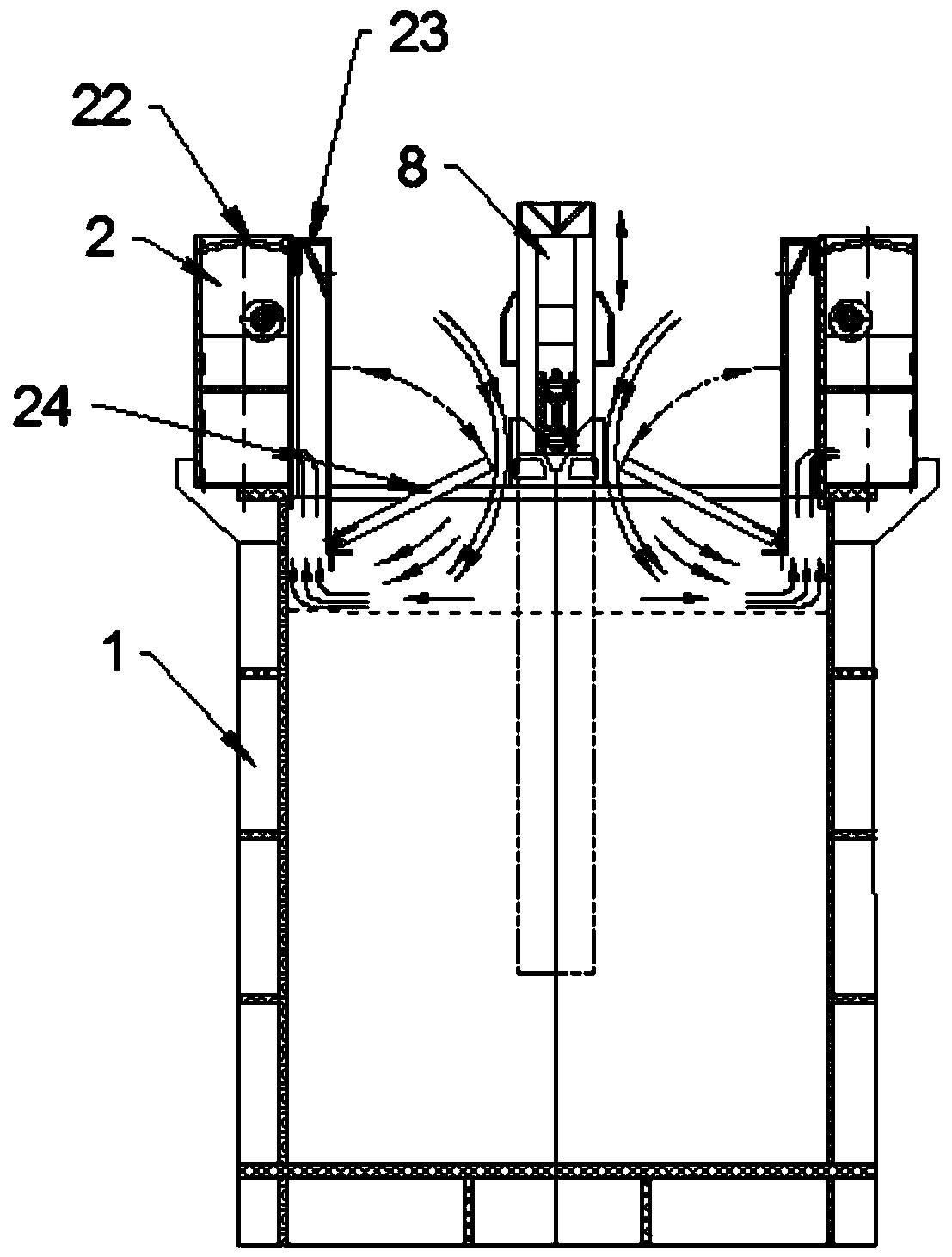
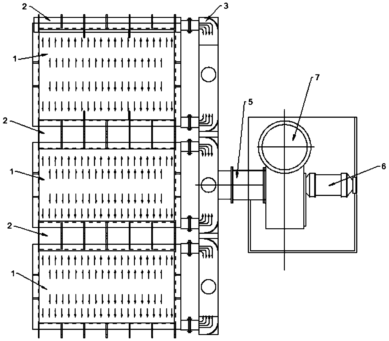
[0073] In the actual work process, such as Figure 1 ~ Figure 3 As shown, the direction of the arrow is a schematic diagram of the flow direction of the gas. The exhaust assembly 2 is arranged on both sides of the upper end of the solution tank 1 of the automatic production line. The drive assembly 21 is placed in the wind cover 22, and the drive motor 211 drives the drive wheel 213 through the drive shaft 212. Rotate, the drive shaft 212 wheel drives the flap 24 to turn over through the drive belt 214, realizing the opening action of the exhaust assembly 2, and the reverse movement can realize the closing action of the exh...


PUM


Abstract

The invention provides an electroplating automatic line exhaust mechanism, and belongs to the field of electroplating equipment. The electroplating automatic line exhaust mechanism comprises exhaust assemblies, single-groove air flues, main air flues and fans, wherein the exhaust assemblies, the single-groove air flues, the main air flues and the fans are arranged on the two sides of the upper ends of solution tanks; each exhaust assembly is arranged corresponding to one single-groove air flue and comprises an air cover, a door cover, an air cover air cavity and an air sucking opening; the airsucking openings communicate with the interiors of the air cavities and the interiors of the solution tanks; one ends of the air cavities communicate with the single-groove air flues which communicate with the main air flues; the fans are arranged at the ends, away from the single-groove air flues, of the main air flues; and the door covers are arranged at the ends, close to the solution tanks, of the air covers, and the height of the lower end faces of the door covers is smaller than that of the air sucking openings. The electroplating automatic line exhaust mechanism is simple in structure,good in air sucking effect, free of leakage, and capable of achieving energy saving and environmental protection.

Description

technical field [0001] The invention belongs to the field of electroplating equipment and relates to an automatic electroplating line exhaust mechanism. Background technique [0002] Electroplating is the process of plating a thin layer of other metals or alloys on the surface of certain metals using the principle of electrolysis. It is a process of using electrolysis to attach a layer of metal film to the surface of metal or other material parts to prevent metal oxidation ( Such as rust), improve wear resistance, electrical conductivity, reflective properties, corrosion resistance (copper sulfate, etc.) and enhance the appearance. [0003] At present, the electroplating process is mostly completed by the electroplating automatic production line. The electroplating production line can be divided into: manual electroplating production line, semi-automatic electroplating production line, and full-automatic electroplating production line. The electroplating production line can ...

Claims


Application Information

Patent Timeline
Patent Type & Authority Applications(China)
IPC IPC(8): C25D21/04
Inventor 庞义
Owner 万向新元绿柱石(天津)科技有限公司
Why Eureka
Try Eureka