
Auxiliary circuit of hybrid DC circuit breaker, method and system for identifying fault nature of multi-terminal flexible DC grid

A DC circuit breaker and auxiliary circuit technology, which is applied in the direction of fault location, power transmission AC network, emergency protection circuit device, etc., can solve the problem of inapplicability of the flexible DC system, achieve high practical value, low additional cost, and high sensitivity Effect

Active Publication Date: 2019-12-06
SHANDONG UNIV
View PDF1 Cites 0 Cited by
  • Summary
  • Abstract
  • Description
  • Claims
  • Application Information

AI Technical Summary

Problems solved by technology

Since there is no coupling relationship between the polar lines after the fault of the flexible DC grid is removed, this method is not applicable to the flexible DC system

Method used


Image

  • Auxiliary circuit of hybrid DC circuit breaker, method and system for identifying fault nature of multi-terminal flexible DC grid
  • Auxiliary circuit of hybrid DC circuit breaker, method and system for identifying fault nature of multi-terminal flexible DC grid
  • Auxiliary circuit of hybrid DC circuit breaker, method and system for identifying fault nature of multi-terminal flexible DC grid

Examples


Embodiment 1

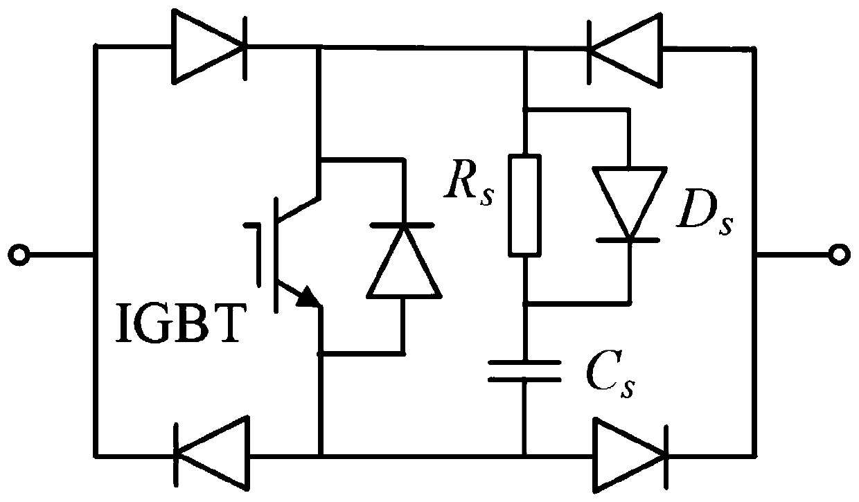
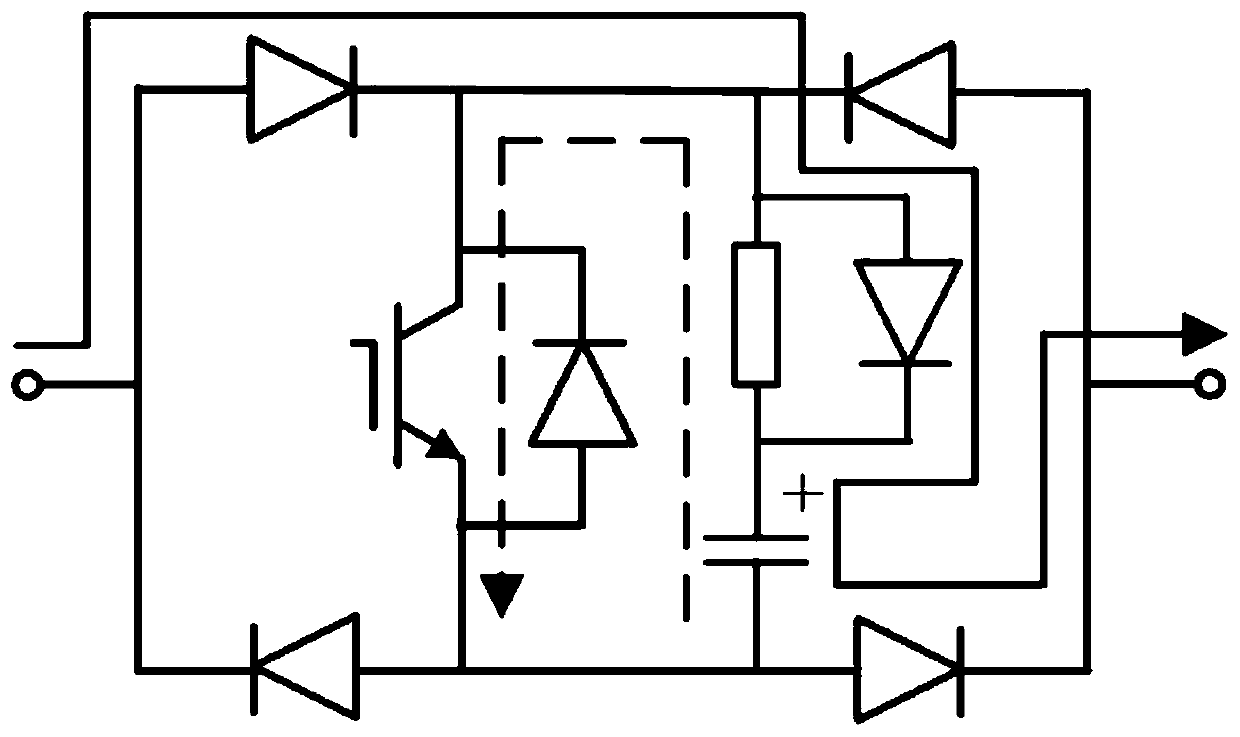
[0055] In one or more embodiments, an auxiliary circuit of a hybrid DC circuit breaker is disclosed, such as Image 6 As shown, the auxiliary circuit is added to the Nc IGBT sub-modules near the overhead line side of the transfer branch of the hybrid DC circuit breaker; the auxiliary circuit includes: a thyristor, a resistor Rg and a fast mechanical switch, and the thyristor is connected in series with the overhead line and the second Between the negative poles of the snubber capacitor of the snubber circuit of an IGBT sub-module and between the snubber capacitors of the snubber circuits of two adjacent IGBT sub-modules, the positive electrode of the snubber capacitor of the Nc-th IGBT sub-module snubber circuit is connected in series with resistors and fast mechanical switches in sequence and ground ; Among them, Nc is the set value.

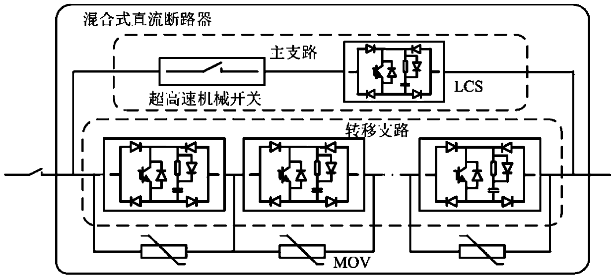
[0056] Hybrid DC circuit breaker is composed of three parts: main branch, transfer branch and metal oxide varistor (MOV), such as figure 1 Shown....

Embodiment 2

[0064] Based on the auxiliary circuit described in the first embodiment, a method for identifying the nature of a fault in a multi-terminal flexible DC grid equipped with a hybrid DC circuit breaker and its application is proposed, such as Picture 10 As shown, including the following steps:

[0065] (1) Configure auxiliary circuit for hybrid DC circuit breaker, auxiliary circuit including thyristor and resistor R g And fast mechanical switch, its structure is like Image 6 Shown

[0066] (2) After the hybrid DC circuit breaker cuts off the fault current, after 200 milliseconds of fault point arc de-free time, trigger signals are first applied to all the thyristors in the auxiliary circuit, and then the fast mechanical switches in the auxiliary circuit are closed;

[0067] (3) Real-time collection of current data on the line side of the hybrid DC circuit breaker;

[0068] (4) Perform wavelet transformation on the current data collected in step (3), and calculate the first-scale wavelet...


PUM


Abstract

An auxiliary circuit for a hybrid direct-current circuit, and a method and system for identifying the property of a fault of a multi-port flexible direct current grid. The auxiliary circuit is added to Nc IGBT sub-modules on a transfer branch of the hybrid direct current circuit breaker close to an overhead line side. The auxiliary circuit comprises: thyristors, a resistor Rg, and a fast mechanical switch. The thyristors are respectively connected in series between an overhead line and a negative electrode of a snubber capacitor of a first IGBT sub-module snubber circuit and between snubber capacitors of two adjacent IGBT sub-module snubber circuits. A positive electrode of a snubber capacitor of an Nc-th IGBT sub-module snubber circuit is sequentially connected in series to the resistor and the fast mechanical switch, and is then grounded wherein Nc is a set value. The auxiliary circuit of the hybrid direct current circuit breaker implements injection of a feature signal to identify transient faults and permanent faults, and can implement the fault localization of the permanent faults.

Description

Technical field [0001] The present invention relates to the technical field of line fault recovery of flexible DC power grids, and in particular to a method and system for identifying the nature of faults in a hybrid DC circuit breaker and a multi-terminal flexible DC power grid. Background technique [0002] The statements in this section merely provide background information related to the present invention, and do not necessarily constitute prior art. [0003] With the development of DC circuit breakers and the requirements of modern power grids for operational flexibility, the multi-terminal flexible DC grid based on overhead lines has outstanding advantages in large-scale clean energy generation and grid connection and large-capacity transmission. It is an important supplement to the AC grid. It is currently under construction. The Zhangbei project is a four-terminal flexible DC grid that transmits power through overhead lines. [0004] The inventor found that, compared with DC...

Claims


Application Information

Patent Timeline
Patent Type & Authority Patents(China)
IPC IPC(8): H02H7/26H02J3/36G01R31/08
CPCG01R31/08H02H7/26H02J3/36Y02E60/60
Inventor 邹贵彬张烁魏秀燕黄强
Owner SHANDONG UNIV
Learn More