
Cool-heat-electricity cogeneration system and method

A technology for combined cooling, heating and power, and air conditioning systems, applied in refrigerators, refrigeration components, refrigeration and liquefaction, etc., can solve problems such as high maintenance costs, insufficient systems, and difficulty in starting, reduce construction and procurement costs, and improve usage. The effect of high efficiency and high system integration

Pending Publication Date: 2019-05-14
SHANGHAI JINPENG TECH CO LTD
View PDF6 Cites 0 Cited by
  • Summary
  • Abstract
  • Description
  • Claims
  • Application Information

AI Technical Summary

Problems solved by technology

In the market, systematic solutions have been provided for power supply, cooling, and heating under driving conditions. The on-board engine can be relied on to drive the air-conditioning mechanical compressor to realize the functions of fresh air, ventilation, cooling, and even heating in the car. The waste heat of the engine is used for heating, and the power supply of the vehicle-mounted electrical equipment is provided through the vehicle-mounted generator and inverter; for the power supply, refrigeration, heating, etc. under the parking condition, the existing scheme is not systematic enough, and there are the following deficiencies, the first , the power supply mainly adopts two schemes to meet the demand, one is to connect to the nearby mains, and the other is to install a vehicle-mounted generator set. According to the electrical standards, the relevant electrical equipment cannot be used normally; in the second scheme, open-frame generator sets are mostly used. Due to the disadvantage of high vibration and noise, the generator set needs to be pulled out and placed at a distance during use, so that the staff Inconvenient to use, pedestrians and surrounding residents will also be affected to varying degrees
Some of them are powered by on-board battery packs, but due to the variety of electrical equipment on the car and the large power consumption, the battery packs can last for a short time, and the maintenance cost is high and the risk is high.
Second, there are mainly two schemes for refrigeration to meet the demand. One is to directly use the driving refrigeration scheme, and the other is to match the household air conditioner in the car. The first scheme requires the continuous operation of the vehicle engine to meet the demand. The consumption is large, the service life will be reduced, and the vibration and noise of the vehicle engine are too large, making the working environment in the vehicle harsh; in the second solution, the household air conditioner needs to occupy part of the space in the vehicle, and the external unit of the air conditioner is installed to dissipate heat The effect has a greater impact and affects the air conditioning effect
Third, there are mainly two schemes for heating to meet the demand, one is to use a fuel heater, and the other is to use a household air conditioner. The first scheme has the problem of difficulty or failure to start when the ambient temperature is low, and the fuel heater emits a lot , will cause serious pollution to the environment; the second option is the same as that described in option 2 in the second problem
This brings inconvenience to users who have such needs, and at the same time fails to meet users' expectations for energy-efficient products

Method used


Image

  • Cool-heat-electricity cogeneration system and method
  • Cool-heat-electricity cogeneration system and method

Examples


Embodiment Construction

[0086] The present invention will be described in detail below in conjunction with specific embodiments. The following examples will help those skilled in the art to further understand the present invention, but do not limit the present invention in any form. It should be noted that those skilled in the art can make several changes and improvements without departing from the concept of the present invention. These all belong to the protection scope of the present invention.

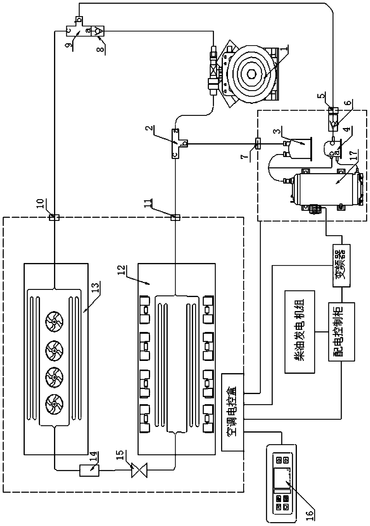
[0087] Such as figure 1 As shown, the present invention provides a combined cooling, heating and power system, including a dual-power air-conditioning system; the dual-power air-conditioning system includes a mechanical compressor 1, a second one-way valve 8, a high-pressure three-way valve 9 and a low-pressure three-way Valve 2; the dual-power air-conditioning system also includes an electric compression group; the electric compression group includes an electric compressor 17, a gas-liquid separator 3,...


PUM


Abstract

The invention provides a cool-heat-electricity cogeneration system. The cool-heat-electricity cogeneration system comprises an electricity supply control system, a dual-power air conditioner system and a residual heat recovery system. According to the cool-heat-electricity cogeneration system, a diesel generating set capable of achieving three-way output simultaneously is provided, and output using of three electric sources is achieved. The cool-heat-electricity cogeneration system has the following advantages that 1, the system is high in integrated degree and can provide electricity supplying, cooling and heating multifunctional ways, and the construction and purchase costs are lowered; 2, the quiet and comfortable environment can be provided for the interior of a vehicle through ultra-silence and low vibration; 3, electricity supplying is more convenient, the long working electric source can be provided for vehicle-mounted electric equipment at any time anywhere, and the problem that a special vehicle difficultly take electricity in the wild or city is solved; and 4, through a dual-power technology, an air conditioner is driven to work by dual power of a mechanical compressor and an electric compressor, in-vehicle cooling can be achieved, and thus an efficient and energy-saving solution is provided for the situations that the electric equipment on the vehicle cannot work andin-vehicle cooling and heating cannot be achieved.

Description

technical field [0001] The present invention relates to the field of an air conditioner for a special vehicle and power distribution for a special vehicle, in particular to a combined cooling, heating and power supply system and a method thereof; in particular, to a vehicle-mounted ultra-quiet combined cooling, heating and power supply system and a method thereof. Background technique [0002] For special vehicles such as medical vehicles, RVs, and communication vehicles, parking work is the norm, so it is necessary to ensure the power consumption of the equipment in the vehicle when parking. At the same time, in order to provide a comfortable working environment for the staff on board, it is also necessary to meet the needs of cooling, heating, ventilation and fresh air in the car when parking. Patent document 1, application number 200810217763.6, publication number CN101418971A, discloses a composite multi-source ground energy central air-conditioning unit, which includes ...

Claims


Application Information

Patent Timeline
IPC IPC(8): B60H1/00B60H1/32F25B13/00F25B41/04F25B31/00F25B49/02F02G5/00F02B63/04F25B41/20
CPCY02E20/14Y02T10/12
Inventor 陈雪峰施春磊钟威李元辉杨智惠方品许俊毅
Owner SHANGHAI JINPENG TECH CO LTD
Learn More