Offshore oil leakage pollutant recycling device
A technology for pollutant recovery and offshore oil, which is applied in water conservancy projects, cleaning of open water surfaces, general water supply conservation, etc., can solve the problems of reducing the practicability of processing devices, low working efficiency of processing devices, and increasing the labor force of staff, so as to prevent Diffusion of pollutants, improvement of pollutant recovery efficiency, and strong wind and wave resistance
- Summary
- Abstract
- Description
- Claims
- Application Information
AI Technical Summary
Problems solved by technology
Method used
Image
Examples
Embodiment 1
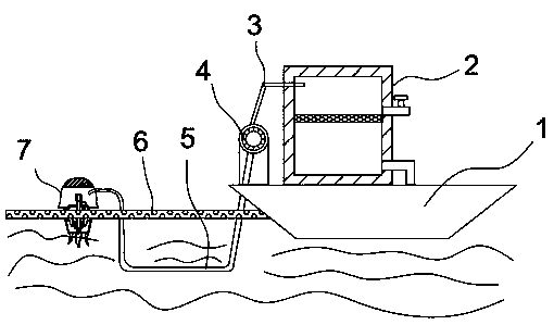
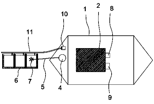
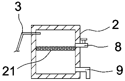
[0025] see Figure 1-5As shown, the offshore oil spill pollutant recovery device includes a hull 1 and an isolation device 6. An oil-water separation box 2 is installed on the upper end of the hull 1, and a liquid pump 4 and an air pump 10 are installed on the bow of the ship on one side of the oil-water separation box 2. The oil-water separation tank 2 is connected to the liquid suction pump 4 through the oil delivery pipe 3, the air pump 10 is connected to the isolation device 6 through the inflatable main pipe 11, and the liquid suction pump 4 is connected to the recovery device 7 in the isolation device 6 through the oil suction pipe 5 placed under water, Install a liquid suction pump at the bow, and connect the liquid suction pump to the recovery device in the isolation device through the underwater oil suction pipe, so that the oil in the isolation device will be sucked into the oil-water separation tank under the action of the liquid suction pump Carry out oil-water sep...
Embodiment 2
[0030] Such as Figure 6-7 As shown, the optimization scheme of this embodiment on the basis of Embodiment 1 is: the recovery device 7 includes an oil storage chamber 71 communicated with the oil suction pipe 5, the upper end of the oil storage chamber 71 is provided with a sensor 72, and the lower end of the oil storage chamber 71 is installed There is a liquid inlet chamber 77, and the inner wall of the liquid inlet chamber 77 is surrounded by an oil-water mixing channel 732 arranged inwardly. Above the oil-water mixing channel 732, there is a suspension arm 74 ring cloth connected to the outer wall of the liquid inlet chamber 77. The oil storage chamber 71 passes through the An oil suction pump 79 is arranged inside to communicate with the top of the liquid inlet chamber 77 . An oil storage chamber connected to the oil suction pipe is set up. The lower end of the oil storage chamber is equipped with a liquid inlet chamber. The inner wall of the liquid inlet chamber is surro...
Embodiment 3
[0037] The working principle of the marine oil spill pollutant recovery device of the present invention is as follows: run the hull 1 to the pollutant leakage site, put the isolation device 6 and the recovery device 7 into the sea surface, control the operation of the air pump 10 through the console on the hull 1, and control the operation of the isolation device 6. The device 6 is inflated to suspend it on the sea surface where the oil leaks, and the control signal is sent to the sensor 72 in the recovery device 7 through the console, and the propeller 75 on the recovery device 7 is controlled to work, so that the recovery device 7 reaches the specified level. The oil pollutants are recovered in the area, and the recovered pollutants are pumped into the oil-water separation tank 2 through the pump 4, and the oil-water separation operation is carried out. The separated oil is discharged from the oil outlet 8, and the separated water is discharged from the oil-water separation ta...
PUM
 Abstract
Description
Claims
Application Information
 - R&D
- Intellectual Property
- Life Sciences
- Materials
- Tech Scout
- Unparalleled Data Quality
- Higher Quality Content
- 60% Fewer Hallucinations
Browse by: Latest US Patents, China's latest patents, Technical Efficacy Thesaurus, Application Domain, Technology Topic, Popular Technical Reports.
© 2025 PatSnap. All rights reserved.Legal|Privacy policy|Modern Slavery Act Transparency Statement|Sitemap|About US| Contact US: help@patsnap.com


