Offshore Oil Spill Pollutant Recovery Device

A technology for pollutant recovery and offshore oil, which is applied in construction, cleaning of open water surfaces, water conservancy projects, etc., can solve the problems of reducing the practicability of the treatment device, increasing the labor force of the staff, and low efficiency of the treatment device, so as to prevent pollutants Diffusion, improve the efficiency of pollutant recovery, and strong wind and wave resistance

Active Publication Date: 2020-04-14
OCEAN RES CENT OF ZHOUSHAN ZHEJIANG UNIV
View PDF6 Cites 1 Cited by
  • Summary
  • Abstract
  • Description
  • Claims
  • Application Information

AI Technical Summary

Problems solved by technology

[0003] Oil pollutants need to use treatment devices in the process of treatment, but the existing treatment devices have low working efficiency, which causes the staff to repeatedly process oil pollutants, which increases the labor force of the staff and wastes a lot of time , which reduces the practicability of the processing device and is not convenient for users to use

Method used


Image

  • Offshore Oil Spill Pollutant Recovery Device
  • Offshore Oil Spill Pollutant Recovery Device
  • Offshore Oil Spill Pollutant Recovery Device

Examples


Embodiment 1

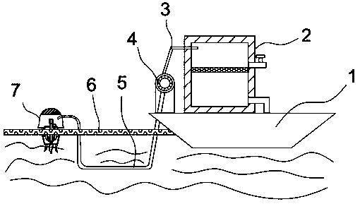
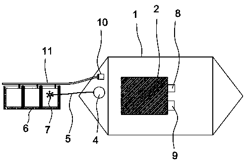
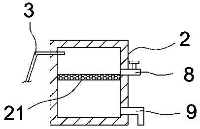
[0025] see Figure 1-5As shown, the marine oil spill pollutant recovery device includes a hull 1 and an isolation device 6. An oil-water separation tank 2 is installed on the upper end of the hull 1, and a liquid pump 4 and an air pump 10 are respectively installed on one side of the oil-water separation tank 2 on the bow of the ship. The oil-water separation tank 2 is connected with the pump 4 through the oil delivery pipe 3, the air pump 10 is connected with the isolation device 6 through the gas main pipe 11, and the liquid pump 4 is connected with the recovery device 7 in the isolation device 6 through the pump pipe 5 placed under water, A pump is installed on the bow of the ship, and the pump is connected to the recovery device in the isolation device through the oil pump placed underwater, so that the oil in the isolation device can be sucked into the oil-water separation tank under the action of the pump. Oil-water separation is carried out, so that the separated oil ca...

Embodiment 2

[0030] like Figure 6-7 As shown, the optimized solution of this embodiment based on Embodiment 1 is: the recovery device 7 includes an oil storage chamber 71 that communicates with the oil pumping pipe 5 , the upper end of the oil storage chamber 71 is provided with a sensor 72 , and the lower end of the oil storage chamber 71 is installed There is a liquid inlet silo 77, the inner side wall of the liquid inlet 77 is surrounded by an oil-water mixing channel 732 arranged inward, and a suspension arm 74 is arranged above the oil-water mixing channel 732 to be connected to the outer side wall of the liquid inlet 77, and the oil storage chamber 71 passes through. An oil suction pump 79 is arranged inside to communicate with the top of the liquid inlet bin 77 . An oil storage chamber connected with the oil pumping pipe is set up, the lower end of the oil storage chamber is installed with a liquid inlet silo, and an oil-water mixing channel arranged inward is arranged around the i...

Embodiment 3

[0037] The working principle of the marine oil spill pollutant recovery device of the present invention is as follows: run the hull 1 to the pollutant leakage site, put the isolation device 6 and the recovery device 7 into the sea, and control the air pump 10 through the console on the hull 1 to work. The device 6 is inflated to make it suspended on the sea surface where the oil leaks, and the control signal is sent to the sensor 72 in the recovery device 7 through the console, and the propeller 75 on the recovery device 7 is controlled to work, so that the recovery device 7 reaches the specified level. The oil pollutants are recovered in the area, and the recovered pollutants are pumped into the oil-water separation box 2 through the liquid pump 4, and the oil-water separation and separation operation is carried out. The separated oil is discharged from the oil outlet 8, and the separated water is removed from the oil-water. The bottom side wall of the separation box 2 is prov...


PUM


Abstract

The invention discloses an offshore oil leakage pollutant recycling device which comprises a ship body and an isolation device, wherein an oil-water separation tank is mounted at the upper end of theship body; a liquid extraction pump and an air pump are arranged on one side of the oil-water separation tank and are mounted on the noise; the oil-water separation tank is connected with the liquid extraction pump through an oil conveying pipe; the air pump is connected with the isolation device through an inflating main pipe; the liquid extraction pump is connected with a recycling device in theisolation device through an oil extraction pipe arranged in water. The offshore oil leakage pollutant recycling device can separate oil from water sucked in the oil-water separation tank, so that theseparated oil can be collected for use, and pollution to the marine environment is reduced; the air pump arranged on the ship body is connected with the isolation device through the inflating main pipe, so that the isolation device can float on the sea surface under the inflating action of the air pump to isolate an oil leakage region; the problem of enlargement of a polluted area and increase ofcollection difficulty due to the fact that the oil is blown away by sea breeze can be prevented, and then the pollutant recycling efficiency of the device is improved.

Description

technical field [0001] The invention belongs to the technical field of oil pollutant treatment, and in particular relates to a pollutant recovery device for marine oil leakage. Background technique [0002] Oil pollution refers to the pollution caused by leakage and discharge of oil in the process of oil extraction, transportation, loading and unloading, processing and use, mainly in the ocean. Oil floats on the sea surface and diffuses rapidly to form an oil film, which can be migrated and transformed through diffusion, evaporation, dissolution, emulsification, photodegradation, and biodegradation and absorption. Oils can adhere to fish gills, suffocate fish, inhibit spawning and hatching of water birds, destroy the impermeability of their feathers, and reduce the quality of aquatic products. The formation of oil film can hinder the re-oxygenation of the water body, affect the growth of marine plankton, destroy the marine ecological balance, and also damage the seaside sce...

Claims


Application Information

Patent Timeline
Patent Type & Authority Patents(China)
IPC IPC(8): E02B15/04E02B15/10
CPCY02A20/204
Inventor 陈磊朱明栋蔡勇戴林伟周晗宇黄海丽
Owner OCEAN RES CENT OF ZHOUSHAN ZHEJIANG UNIV
Why Eureka
Try Eureka