Tab molding mechanism, molding method and tab molding equipment

A molding mechanism and lug technology, applied in structural parts, sustainable manufacturing/processing, electrical components, etc., can solve problems such as insufficient energy utilization, uneven temperature distribution, and low production efficiency, and achieve uniform current distribution and heating Good effect, the effect of improving production efficiency

Pending Publication Date: 2019-05-17
深圳市鑫科高创科技有限公司
View PDF0 Cites 0 Cited by
  • Summary
  • Abstract
  • Description
  • Claims
  • Application Information

AI Technical Summary

Problems solved by technology

[0007] In order to overcome the disadvantages of low production efficiency, uneven temperature distribution, insufficient energy utilization and poor glue quality of the existing thermal compounding method, the invention provides a tab forming mechanism, a forming method and a tab forming equipment. When passing through the conductor, the conductor heats up and the temperature rises based on the principle of current thermal effect. Using a DC power supply, the current flows into the parts of the metal strips on both sides of the tabs that are not provided with tabs, so that the metal strips between the first electrode and the second electrode quickly Reach the temperature required for thermal compounding, effectively improve production efficiency, improve product quality, and reduce energy loss

Method used


Image

  • Tab molding mechanism, molding method and tab molding equipment
  • Tab molding mechanism, molding method and tab molding equipment
  • Tab molding mechanism, molding method and tab molding equipment

Examples


Embodiment 1

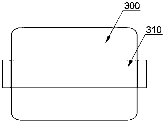
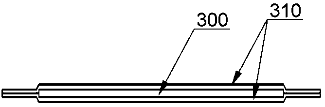
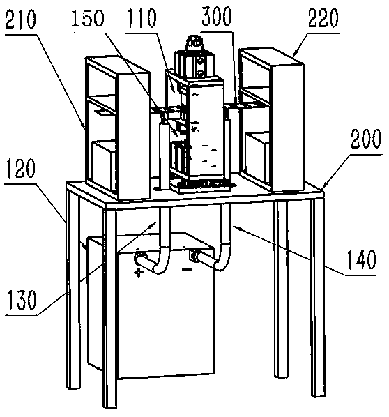
[0041] An embodiment of the present invention provides a tab forming mechanism for figure 1 , figure 2 The thermal compounding process of the metal strip 300 and the tab glue 310 is shown, wherein the metal strip 300 is stretched into a strip shape from the metal strip 300 rolled in the previous process 210 by self-heating, and several pairs of the tab glue 310 and the metal The length direction of the strip 300 is vertical and arranged on the upper and lower surfaces of the metal strip 300 at intervals, and the tab glue 310 on the same side of the metal strip 300 is attached to each other at the position extending out of the metal strip 300 ( figure 2 , Figure 6 shown in ). see Figure 3-Figure 6 , the tab forming mechanism includes a DC power supply 120, a pressing mechanism 110 formed above the metal strip 300, and a conductive mechanism 150 formed below the metal strip 300, and the conductive mechanism 150 includes a first electrode 8 and a second electrode 9 The fi...

Embodiment 2

[0056] Embodiment 2 of the present invention discloses the tab forming method of the tab forming mechanism described in Embodiment 1, which is used in the thermal compounding process of metal strip 300 and tab glue 310, including the following steps:

[0057] Step S1: The pressed metal strip 300 and the ear glue 310 are threaded between the conductive mechanism 150 and the pressing mechanism 110, and the first electrode 8 and the second electrode 9 are aligned on both sides of the ear glue 310, corresponding to The metal strip 300 is not provided with the position setting of the ear glue 310;

[0058]Step S2: the first cylinder 5 operates, the first electrode 8 and the second electrode 9 rise and contact the metal strip 300;

[0059] Step S3: the second air cylinder 15 operates, the first pressing block 17 and the second pressing block 18 descend to press the metal strip 300 onto the first electrode 8 and the second electrode 9;

[0060] Step S4: Turn on the DC power supply 1...

Embodiment 3

[0067] Embodiment 3 of the present invention discloses a tab forming device, which includes the tab forming mechanism described in Embodiment 1. The tab forming equipment also includes a tab forming mechanism and a cutting mechanism after thermally laminating the metal strip 300 and the tab glue 310 . In the embodiment of the present invention, a plurality of lugs 310 on the metal strip 300 are thermally compounded on the metal strip 300, and then cutting and other processes are performed to effectively improve product production efficiency and product qualification rate.


PUM


Abstract

The invention discloses a tab molding mechanism, molding method and tab molding equipment. The tab molding mechanism comprises a DC power supply, a laminating mechanism formed on a metal belt, and a conducting mechanism formed below the metal belt; the conducting mechanism comprises a first electrode and a second electrode arranged at the locations without tab sealant on the corresponding metal belt at two sides of the tab sealant; the positive electrode of the DC power supply is connected with the first electrode, and the negative electrode of the DC power supply is connected with the secondelectrode; in the thermal compounding, the laminating mechanism and the conducting mechanism are adhered at the metal belt locations at two sides of the tab sealant; a loop is formed among the positive electrode of the DC power supply, the first electrode, the metal belt, the second electrode and the negative electrode of the DC power supply; the DC power supply outputs the current, and the metalbelt between the first electrode and the second electrode are heated under the current thermal effect so that the tab sealant is hot-molten on the metal belt; the production efficiency is effectivelyimproved, the product quality is improved, and the energy loss is reduced.

Description

technical field [0001] The invention relates to the technical field of tab manufacturing for power batteries, and more particularly relates to a tab forming mechanism, a forming method, and tab forming equipment. Background technique [0002] Lithium-ion polymer power batteries are widely used in electric vehicles, backup power supplies, etc., and are an important branch of new energy vehicle batteries. The power tab (hereinafter referred to as the tab) is a key part of the battery, which is made of a chemically treated metal sheet (aluminum or copper nickel-plated) and a pair of tab glue formed on the upper and lower surfaces of the metal sheet. Such as figure 1 , figure 2 shown. The quality of the tab directly affects the performance of the battery, especially the safety and service life. [0003] Tab forming refers to the chemically treated metal strip and tab film as materials, the metal strip and tab glue are fused by heating (hereinafter referred to as thermal com...

Claims


Application Information

Patent Timeline
Patent Type & Authority Applications(China)
IPC IPC(8): H01M2/26H01M10/058H01M50/531
CPCY02E60/10Y02P70/50
Inventor 朱健锋陈毅斌
Owner 深圳市鑫科高创科技有限公司
Why Eureka
Try Eureka