Bidirectional DC-DC circuit topology structure and control method in bidirectional charger

A circuit topology, DC-DC technology, applied in the direction of battery circuit devices, circuit devices, control/regulation systems, etc., can solve the problems of high cost, potential safety hazards, and large power variation range, and achieve the goal of reducing the withstand voltage level Requirements, improve the efficiency of electric energy utilization, and avoid the effect of high-frequency circulation

Inactive Publication Date: 2019-05-17
YANGZHOU UNIV +1
View PDF5 Cites 2 Cited by
  • Summary
  • Abstract
  • Description
  • Claims
  • Application Information

AI Technical Summary

Problems solved by technology

The first method mostly uses a bidirectional half-bridge circuit. When the voltage of the battery pack is low, the energy conversion efficiency of this circuit is relatively low when the voltage of the battery pack is relatively large compared to the high-voltage DC voltage on the input side. In addition, the battery and the DC bus There is no electrical isolation between them, and there are potential safety hazards
In the second method, a full-bridge circuit is mostly used. Both ends of the high-frequency isolation transformer adopt a full-bridge structure, and a bidirectional circuit topology based on LLC is also used. However, it is difficult to achieve soft switching when the full-bridge circuit is light-loaded, and the LLC circuit is light-loaded. High frequency, large loss
At present, in the application of bidirectional chargers, a better circuit topology is to use a dual active bridge circuit. However, with the improvement of the degree of integration and the battery voltage range, and the power variation range during the battery charging process is already very large, For a charger with a fixed circuit structure, the switching devices in the circuit must be selected according to the maximum withstand voltage and current, so such a charger not only has high cost, but also has low power conversion efficiency.
If a product is developed separately for applications with different voltage levels and different power levels, although higher efficiency can be obtained, the production cost will increase, resulting in low economic benefits for manufacturers.

Method used


Image

  • Bidirectional DC-DC circuit topology structure and control method in bidirectional charger
  • Bidirectional DC-DC circuit topology structure and control method in bidirectional charger
  • Bidirectional DC-DC circuit topology structure and control method in bidirectional charger

Examples


Embodiment Construction

[0051] The present invention will be further described below in conjunction with specific embodiments.

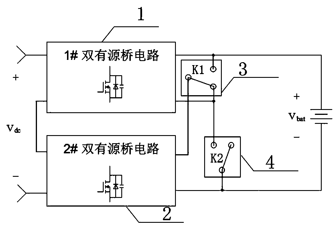
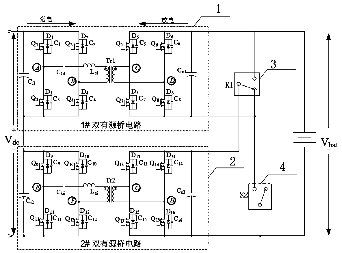
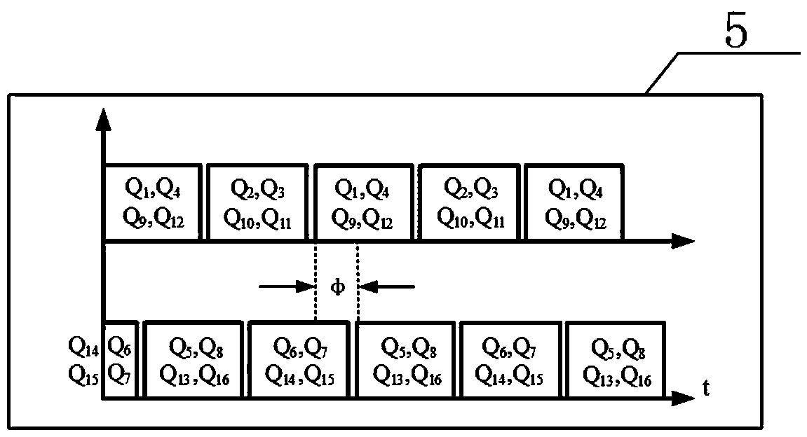
[0052] Such as figure 1 , figure 2 , image 3 and Figure 4 As shown: the system is composed of a first dual active bridge circuit 1, a second dual active bridge circuit 2, a relay 3, a relay 4 and a switching tube driving pulse signal 5.

[0053] Depend on figure 1 and figure 2 Shown: a bidirectional DC-DC circuit topology in a bidirectional charger, including the first dual active bridge circuit 1 and the second dual active bridge circuit 2, the first dual active bridge circuit 1 and the second dual active bridge circuit The bridge circuit 2 is connected to the high-voltage input DC side after being connected in series at the input end, and the first dual active bridge circuit 1 and the second dual active bridge circuit 2 are connected to the battery after being connected in series or in parallel through the relay 3 and the relay 4 at the output end.

[0054] The ...


PUM


Abstract

The invention discloses a bidirectional DC-DC circuit topology structure in a bidirectional charger in the field of chargers. The bidirectional DC-DC circuit topology structure in the bidirectional charger comprises two dual active bridge circuits and two relays; the input sides of the first dual active bridge circuit and the second dual active bridge circuit are connected in series and then connected to a high-voltage DC side; one end output of the first dual active bridge circuit is connected to a normally open contact of the first relay and is connected to a positive pole of a battery; theother end output of the first dual active bridge circuit is connected to a normally closed contact of the first relay; one end output of the second dual active bridge circuit is connected to a commonterminal of the first relay, and the other end output of the second dual active bridge circuit is connected to the common terminal of the second relay and connected to the negative pole of the battery; and the normally closed contact of the first relay is connected to the normally open contact of the second relay. The invention adopts two dual active bridge circuits to connect in series on the high-voltage DC side, and then connects the battery after realizing series or parallel connection of the output ends through the control relays; therefore, the cost is reduced, and the power conversion efficiency is improved.

Description

technical field [0001] The invention relates to a charger, in particular to a circuit structure of a bidirectional charger. Background technique [0002] There are mainly two types of bidirectional DC-DC converters currently used in bidirectional charger circuits: 1) DC-DC bidirectional converters that are not electrically isolated, and 2) isolated DC-DC bidirectional converters. The first method mostly uses a bidirectional half-bridge circuit. When the voltage of the battery pack is low, the energy conversion efficiency of this circuit is relatively low when the voltage of the battery pack is relatively large compared to the high-voltage DC voltage on the input side. In addition, the battery and the DC bus There is no electrical isolation between them, which poses a safety hazard. In the second method, a full-bridge circuit is mostly used. Both ends of the high-frequency isolation transformer adopt a full-bridge structure, and a bidirectional circuit topology based on LLC ...

Claims


Application Information

Patent Timeline
Patent Type & Authority Applications(China)
IPC IPC(8): H02M3/335H02J7/00
Inventor 方宇任俊张倩张继勇
Owner YANGZHOU UNIV
Why Eureka
Try Eureka